EM785830AA
8-bit Micro-controller
VII.5 RESET
The RESET can be caused by
(1) Power on reset
(2) WDT timeout. (if enabled and in GREEN or NORMAL mode)
(3) /RESET pin pull low
Once the RESET occurs, the following functions are performed.
•The oscillator is running, or will be started.
•The Program Counter (R2) is set to all "0".
•When power on, the upper 3 bits of R3 and the upper 2 bits of R4 are cleared.
•The Watchdog timer and prescaler counter are cleared.
•The Watchdog timer is disabled.
•The CONT register is set to all "1"
•The other register (bit 7 ~ bit 0) default values are as follows.
Operation registers :
Address
R register
PAGE0
R register
PAGE1
R register
PAGE2
R register
PAGE3
IOC register
IOC register
PAGE1
PAGE0
0x4
0x5
0x6
0x7
0x8
0x9
0xA
0xB
0xC
0xD
0xE
0xF
00xxxxxx
xxxx0000
xxxxxxxx
xxxxxxxx
xxxxxxxx
xxxxxxxx
00011xx0
xxxxxxxx
xxxxxxxx
xxxxx000
00000000
00000000
xxxx0000
xxxxxxxx
xxxx0000
00000000
xxxxxxxx
11111111
xxxxxxxx
00000000
00000000
00000000
xxxxxxxx
00000000
00000000
xxxxxx00
00000000
00000000
xxxxxx00
00000000
111x0000
11111111
11111111
11111111
11111111
xxxxxxxx
11111111
11111111
xxxxxxxx
0000xxxx
00000000
00000000
00000000
00000000
00000000
x0xx0xx
0x000000
xxxxxxxx
xxxxxxxx
xxxxxxxx
xxxxxxxx
000000x0
00000000
00000000
xxxxxxxx
VII.6 Wake-up
The controller provided sleep mode for power saving :
SLEEP mode, RA(7) = 0 + "SLEP" instruction
The controller will turn off all the CPU and crystal. Other circuit with power control like key tone control or
PLL control (which has enable register), user has to turn it off by software.
Wake-up from SLEEP mode
(1) WDT time out
(2) External interrupt
(3) /RESET pull low
All these cases will reset controller , and run the program at address zero. The status just like the power on reset.
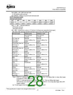
VII.7 Interrupt
RF is the interrupt status register which records the interrupt request in flag bit. IOCF is the interrupt mask
register. Global interrupt is enabled by ENI instruction and is disabled by DISI instruction. When one of the
interrupts (when enabled) generated, will cause the next instruction to be fetched from address 008H. Once in the
interrupt service routine, the source of the interrupt can be determined by polling the flag bits in the RF register.
The interrupt flag bit must be cleared in software before leaving the interrupt service routine and enabling
interrupts to avoid recursive interrupts.
__________________________________________________________________________________________________________________________________________________________________
* This specification is subject to be changed without notice.
28
12/1/2004 V1.6

 ELAN [ ELAN MICROELECTRONICS CORP ]