EM785830AA
8-bit Micro-controller
Fosc
1:2
To PWM1IF
1:8
1:32
1:64
MUX
reset
Period
Match
TMR1X
Comparator
T1P0 T1P1
T1EN
PRD1
Data Bus
Data Bus
PRD2
T2P0 T2P1 T2EN
Comparator
reset
Period
Match
Fosc
1:2
TMR2X
1:8
1:32
1:64
MUX
To PWM2IF
*TMR1X = TMR1H + TMR1L;
*TMR2X = TMR2H +TMR2L
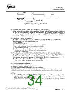
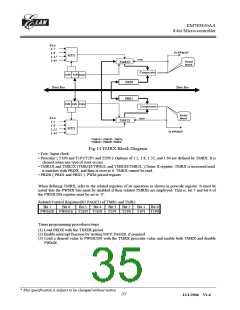
Fig.14 TMRX Block Diagram
• Fosc: Input clock.
• Prescaler ( T1P0 and T1P1/T2P1 and T2P0 ): Options of 1:2, 1:8, 1:32, and 1:64 are defined by TMRX. It is
cleared when any type of reset occurs.
• TMR1X and TMR2X (TMR1H/TWR1L and TMR2H/TMR2L ):Timer X register; TMRX is increased until
it matches with PRDX, and then is reset to 0. TMRX cannot be read.
• PRDX ( PRD1 and PRD2 ): PWM period register.
When defining TMRX, refer to the related registers of its operation as shown in prescale register. It must be
noted that the PWMX bits must be disabled if their related TMRXs are employed. That is, bit 7 and bit 6 of
the PWMCON register must be set to ‘0’.
Related Control Registers(R5 PAGE3) of TMR1 and TMR2
Bit 7
Bit 6
Bit 5
Bit 4
Bit 3 Bit 2
Bit 1 Bit 0
T1P1 T1P0
PWM2E PWM1E T2EN T1EN T2P1 T2P0
Timer programming procedures/steps
(1) Load PRDX with the TIMER period.
(2) Enable interrupt function by writing IOCF PAGE0, if required
(3) Load a desired value to PWMCON with the TMRX prescaler value and enable both TMRX and disable
PWMX.
__________________________________________________________________________________________________________________________________________________________________
* This specification is subject to be changed without notice.
33
12/1/2004 V1.6

 ELAN [ ELAN MICROELECTRONICS CORP ]