EM785830AA
8-bit Micro-controller
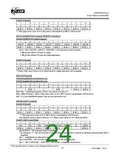
RE (Interrupt flag)
PAGE0 (Interrupt flag)
7
6
RBF
R/W-0
5
ADI
R/W-0
4
3
0
2
0
1
0
0
0
PWM2
R/W-0
PWM1
R/W-0
R/W-0
R/W-0
R/W-0
R/W-0
Bit0 ~ Bit3 : These three bits must clear to 0 or unable to expect error will occur .
Bit 4(PWM1) : PWM1 one period reach interrupt flag.
Bit 5 (ADI) : ADC interrupt flag after a sampling
Bit 6 (RBF) : SPI data transfer complete interrupt
If SPI's RBF signal has a rising edge signal (RBF set to "1" when transfer data completely), CPU will set
this bit.
Bit 7(PWM2) : PWM2 one period reach interrupt flag.
PAGE2,3 (undefined) not allowed to use. This page is not sure to 0 or 1
RF (Interrupt status)
(Interrupt status register)
7
6
-
5
4
3
2
1
0
INT3
R/W-0
-
-
INT0
R/W-0
CNT2
R/W-0
CNT1
R/W-0
TCIF
R/W-0
"1" means interrupt request, "0" means non-interrupt
Bit 0(TCIF) : TCC timer overflow interrupt flag
Set when TCC timer overflows.
Bit 1(CNT1) : counter1 timer overflow interrupt flag
Set when counter1 timer overflows.
Bit 2(CNT2) : counter2 timer overflow interrupt flag
Set when counter2 timer overflows.
Bit 3(INT0) : external INT0 pin interrupt flag
If PORT70 has a falling edge/rising edge (controlled by CONT register) trigger signal, CPU will set this bit.
Bit 4~6: Unused (These bits are not sure to 0 or 1. When programmer determine what interrupt occur in
subroutine, be care to note these bits)
Bit 7(INT3) : external PORT73 pin interrupt flag
<Note> IOCF is the interrupt mask register. User can read and clear.
Trigger edge as the table
Signal
Trigger
TCC
Time out
Time out
Time out
Falling
COUNTER1
COUNTER2
INT0
Rising edge
Falling edge
INT3
R10~R3F (General Purpose Register)
R10~R3F (Banks 0 ~ 3) : all are general purpose registers.
__________________________________________________________________________________________________________________________________________________________________
* This specification is subject to be changed without notice.
18
12/1/2004 V1.6

 ELAN [ ELAN MICROELECTRONICS CORP ]