EM73962A
4-BIT MICROCONTROLLER
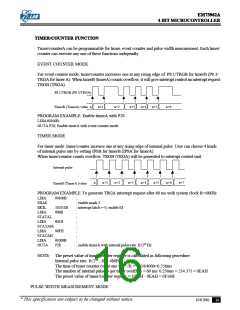
For the pulse width measurement mode, the counter only incresed by the rising edge of internal pulse rate as
external timer/counter input (P8.1/TRGB, P8.3/TRGA ), interrupt request will be generated as soon as
timer/counter count overflow.
P8.1/TRGB(P8.3/TRGA)
Internal pulse
n
n+1
n+2
n+3
n+4
n+5
TimerB(TimerA) value
PROGRAM EXAMPLE: Enable timerA by pulse width measurement mode.
LDIA
OUTA
#1100b
P28
;
; Enable timerA with pulse width measurement mode.
INTERRUPT FUNCTION
There are 5 interrupt sources, 2 external interrupt sources, 3 internal interrupt sources. Multiple interrupts
are admitted according the priority.
Type
Interruptsource
Priority Interrupt
Latch
Interrupt
Enablecondition
ProgramROM
entryaddress
External Externalinterrupt(INT0)
Internal Reserved
Internal TimerAoverflowinterrupt(TRGA)
Internal TimerBoverflowinterrupt(TRGB)
Internal Time base interrupt(TBI)
External Externalinterrupt(INT1)
1
2
3
4
5
6
IL5
IL4
IL3
IL2
IL1
IL0
EI=1
002h
004h
006h
008h
00Ah
00Ch
EI=1,MASK3=1
EI=1,MASK2=1
EI=1,MASK1=1
EI=1,MASK0=1
INTERRUPT STRUCTURE
MASK0 MASK1 MASK1 MASK2 MASK3
TRGB
r2
TRGA
r3
INT1
r0
TBI
r1
INT0
r5
r4
IL4
Reset by system reset and program
instruction
IL0
IL1
IL2
IL3
IL5
Priority checker
Reset by system reset and program
instruction
Set by program instruction
EI
Entry address generator
Interrupt entry address
Interrupt request
Interrupt controller:
IL0-IL5
: Interrupt latch. Hold all interrupt requests from all interrupt sources. ILr can not be
set by program, but can be reset by program or system reset, so IL only can decide
which interrupt source can be accepted.
MASK0-MASK3 : Except INT0 ,MASK register can promit or inhibit all interrupt sources.
* This specification are subject to be changed without notice.
10.8.2001
17

 ELAN [ ELAN MICROELECTRONICS CORP ]