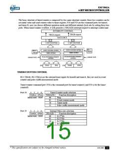
EM73962A
4-BIT MICROCONTROLLER
There is one kind of sleep/hold release mode.
Edge release mode:
Release sleep/hold condition by the falling edge of any one of P0(0..3)/WAKEUP0..3 or P8(0..3)/
WAKEUPA..D.
Note : There are 8 independent mask options for wakeup function in EM73962A. So, the wakeup function
of P0(0..3)/WAKEUP0..3 and P8(0..3)/WAKEUPA..D are enabled or disabled independently.
LCD DRIVER
It can directly drive the liquid crystal display ( LCD ) and has 40 segments, 8 commons output pins.
There are total 40x8 dots can be display.
(1) LCD driver control command register:
Port27 3
LDC
2
1
*
0
*
Initial value: 0h
LCD DISPLAY CONTROL
LDC
0 0
0 1
1 0
1 1
Function description
LCD display disable
Blanking, change COMMON pin output
Reserved
LCD display enable
* : Don't care.
P27 is the LDC driver control command register . The initial value is 0000.
When LDC ( bit2 and bit3 of P27 ) is set to "00", the LCD display is disabled.
When LDC is set to "01", the LCD is blanking, the COM pins are inactive and the SEG pins continuously
output the display data.
The power switch of LCD driver is turned off when the CPU is reseted.
When LDC is set to "11", the LCD display is enabled, the power switch is turned on and it can not be turned
off forever except the CPU is reseted again.
The power switch is also turned off during the sleep operation. Users must enable the LCD display again
by self when the CPU is waked up.
(2) LCD display data area:
The LCD display data is stored in the display data area of the data memory (RAM).
The display data area begins with address 20H during reset. The LCD display data area is as below:
RAM
0
1
2
3
4
5
6
7
8
9
A
B
C
D
E
F
20H
30H
40H
50H
60H
70H
80H
90H
C O M 0
C O M 1
C O M 2
C O M 3
C O M 4
C O M 5
C O M 6
C O M 7
SSSS SSSS SS SS SSSS SSSS SSS S SSSS SSSS SSSS SSSS
EEEE EEEE EE EE EEEE EEEE EEE E EEEE EEEE EEEE EEEE
GGGG GGGGGGGG GGGG GGGG GGGG GGGG GGGG GGGG GGGG
0 1 2 3 4 5 6 7 8 9 1 1 1 1 1 1 1 1 1 1 2 2 2 2 2 2 2 2 2 2 3 3 3 3 3 3 3 3 3 3
0 1 2 3 4 5 6 7 8 9 0 1 2 3 4 5 6 7 8 9 0 1 2 3 4 5 6 7 8 9
bbbb
i i i i
t t t t
0123
* This specification are subject to be changed without notice.
10.8.2001
19

 ELAN [ ELAN MICROELECTRONICS CORP ]