EM73962A
4-BIT MICROCONTROLLER
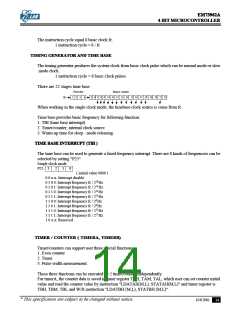
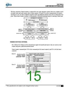
The basic structure of timer/counter is composed by two same structure counter, these two counters can be
set initial value and send counter value to timer register, P28 and P29 are the command ports for timerA
and timer B, user can choose different operation mode and different internal clock rate by setting these two
ports. When timer/counter overflow, it will generate a TRGA(B) interrupt request to interrupt control unit.
INTERRUPT CONTROL
TRGB request
TRGA request
DATA BUS
12 BIT COUNTER
12 BIT COUNTER
P8.1/
TRGB
EVENT COUNTER CONTROL
TIMER CONTROL
EVENT COUNTER CONTROL
TIMER CONTROL
P8.3/
TRGA
PULSE-WIDTH MEASUREMENT
CONTROL
PULSE-WIDTH MEASUREMENT
CONTROL
internal clock
internal clock
TMSA
IPSA
TMSB
IPSB
P28
P29
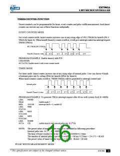
TIMER/COUNTER CONTROL
P8.1/TRGB, P8.3/TRGA are the external timer inputs for timerB and timerA, they are used in event
counter and pulse-width measurement mode.
Timer/counter command port: P28 is the command port for timer/counterA and P29 is for the timer/
counterB.
Port 28
3
2
1
0
Timer/Counter mode selection
TMSA IPSA TMSA(B) Function description
Stop
Initial state : 0000
00
01
10
11
Event counter mode
Timer mode
Pulse width measurement mode
Port 29
3
2
1
0
Internal Pulse-rate selection
TMSB IPSB
Initial state : 0000
IPSA(B)
Function description
00
01
10
11
fc/210Hz
fc/214Hz
fc/218Hz
fc/222Hz
* This specification are subject to be changed without notice.
10.8.2001
15

 ELAN [ ELAN MICROELECTRONICS CORP ]