EM73962A
4-BIT MICROCONTROLLER
The instruction cycle equal 8 basic clock fc.
1 instruction cycle = 8 / fc
TIMING GENERATOR AND TIME BASE
The timing generator produces the system clock from basic clock pulse which can be normal mode or slow
mode clock.
1 instruction cycle = 8 basic clock pulses
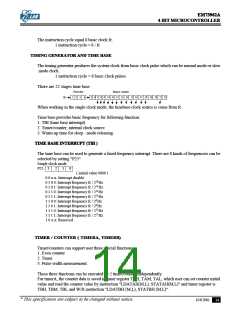
There are 22 stages time base.
Prescaler
Binary counter
1
2
3
4
5
6
7
8
9
10 11 12 13 14 15 16 17 18 19 20 21 22
fc
When working in the single clock mode, the timebase clock source is come from fc.
Time base provides basic frequency for following function:
1. TBI (time base interrupt).
2. Timer/counter, internal clock source.
3. Warm-up time for sleep - mode releasing.
TIME BASE INTERRUPT (TBI )
The time base can be used to generate a fixed frequency interrupt. There are 8 kinds of frequencies can be
selected by setting "P25"
Single clock mode
P25
3
2
1
0
( initial value 0000 )
0 0 x x: Interrupt disable
0 1 0 0: Interrupt frequency fc / 210 Hz
0 1 0 1: Interrupt frequency fc / 211 Hz
0 1 1 0: Interrupt frequency fc / 212 Hz
0 1 1 1: Interrupt frequency fc / 213 Hz
1 1 0 0: Interrupt frequency fc / 29 Hz
1 1 0 1: Interrupt frequency fc / 28 Hz
1 1 1 0: Interrupt frequency fc / 215 Hz
1 1 1 1: Interrupt frequency fc / 217 Hz
1 0 x x: Reserved
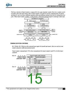
TIMER / COUNTER ( TIMERA, TIMERB)
Timer/counters can support user three special functions:
1. Even counter
2. Timer.
3. Pulse-width measurement.
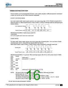
These three functions can be executed by 2 timer/counter independently.
For timerA, the counter data is saved in timer register TAH, TAM, TAL, which user can set counter initial
value and read the counter value by instruction "LDATAH(M,L), STATAH(M,L)" and timer register is
TBH, TBM, TBL and W/R instruction "LDATBH (M,L), STATBH (M,L)".
* This specification are subject to be changed without notice.
10.8.2001
14

 ELAN [ ELAN MICROELECTRONICS CORP ]