VS1005g Datasheet
10 VS1005 PERIPHERALS AND REGISTERS
decoder. When both ready register are set the error correcting agorithm has completed and an
interrupt request is generated.
RS_ST_DFAIL is set when a fatal error was encountered. It is not possible to restore code
word. RS_ST_DFAIL is modified after code end was given (RS_CF_DEND set by user)
RS_ST_DERR flag is set if code word has errors. RS_ST_DERR is modified after code end
was given (RS_CF_DEND was set by user). If this flag was set the error correcting algorithm
is started automatically.
RS_ST_DOK flag is set if code word does not has errors. RS_ST_DOK is modified after code
end was given (RS_CF_DEND was set by user).
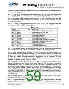
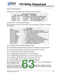
RS_CF Bits
Name
Bits Description
RS_CF_DNF
13 R-S decoder nand flash mode select
12 R-S decoder 10-bit input data
11 R-S decoder code end
RS_CF_D10B
RS_CF_DEND
RS_CF_DSTR
RS_CF_DENA
RS_CF_DMODE
RS_CF_SEL[3:0]
RS_CF_ENF
RS_CF_ESTR
RS_CF_EENA
RS_CF_EMODE
10 R-S decoder code start
9
8
R-S decoder enable
R-S decoder mode control
7:4 R-S encoder parity select for RS_OPORT
3
2
1
0
R-S encoder nand flash mode select
R-S encoder code start
R-S encoder enable
R-S encoder mode control
RS_CF_DNF selects between two data input modes. When set the decoder uses nand flash
input data register as input. When reset the data is fetched from peripheral memory.
RS_CF_D10B selects between 10-bit and 8-bit input modes. Normally the symbols are 8-bit
and two MSB zero bits are added. When RS_CF_D10B is set the symbols are fetched from
peripheral memory as 10-bit and the two MSB bits are not zeroed. In 10-bit mode the data
is in bits [9:0] and it is fetched from memory in word format. This bit is set when NF parity
check symbols are decoded. When decoding the 10-bit check symbols the decoder does not
generate RS decoder interrupt DSPI_ST_RSDEC.
RS_CF_DEND is a code end register for decoder. When this register is set the decoder stops
decoding current code word and the status can be read from RS_ST register. If code word
contained symbol errors the symbol error correction algorithm is started automatically. The
location and magnitude pairs needed to fix corrupted symbols are placed in memory from
RS_DPNTR address onwards. The RS_DPNTR value is not incremented during calculation
and it holds the start address of the location / magnitude pairs in memory. The progress of the
calculation is visible in RS_ST register. When the location / magnitude pairs are calculated an
DSPI_ST_BMCSF interrupt is generated. RS_CF_DEND register is automatically reset after
one clock cycle.
RS_CF_DSTR initializes the R-S decoder i.e. starts a new decoding sequence. This register
is reset automatically when first symbol is decoded.
RS_CF_DENA enables the R-S decoder. When RS_CF_DNF is set the decoder is decoding
symbols as they are read from nand flash. If RS_CF_DNF is reset the decoder starts read-
Version: 0.2, 2012-03-16
59

 ETC [ ETC ]