NE555/SA555/NA555
PRECISION TIMERS
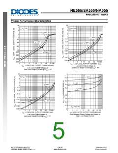
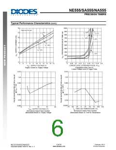
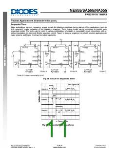
Typical Applications Characteristics
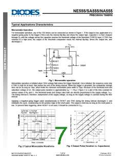
Monostable Operation
For monostable operation, any of the ‘555 timers can be connected as shown in Figure 1. If the output is low, application of a
negative-going pulse to the trigger (TRIG) sets the internal flip-flop and drives the output high. Capacitor C is then charged
through RA until the voltage across the capacitor reaches the threshold voltage of the threshold (THRES) input. If TRIG has
returned to a high level, the output of the threshold comparator resets the internal flip-flop, drives the output low, and
discharges C.
VCC
(5V to 15V)
RA
RL
5
8
VCC
CONT
4
7
RESET
3
DISCH
Output
OUT
6
2
THRES
TRIG
Input
C
GND
1
Fig 1. Monostable operation
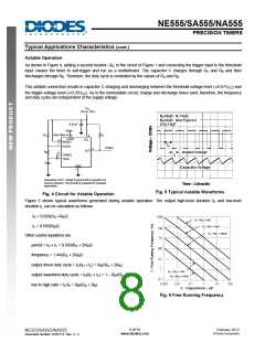
Monostable operation is initiated when TRIG voltage falls below the trigger threshold. Once initiated, the sequence ends only
if TRIG is high for at least 10μs before the end of the timing interval. When the trigger is grounded, the comparator storage
time can be as long as 10μs, which limits the minimum monostable pulse width to 10μs. Because of the threshold level and
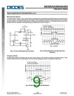
saturation voltage of Q1, the output pulse duration is approximately tW = 1.1RAC. Figure 3 is a plot of the time constant for
various values of RA and C. The threshold levels and charge rates both are directly proportional to the supply voltage, VCC
.
The timing interval is, therefore, independent of the supply voltage, so long as the supply voltage is constant during the time
interval.
Applying a negative-going trigger pulse simultaneously to RESET and TRIG during the timing interval discharges C and
reinitiates the cycle, commencing on the positive edge of the reset pulse. The output is held low as long as the reset pulse is
low. To prevent false triggering, when RESET is not used, it should be connected to VCC
.
Fig. 3 Output Pulse Duration vs. Capacitance
Fig. 2 Typical Monostable Waveforms
7 of 14
www.diodes.com
February 2012
© Diodes Incorporated
NE555/SA555/NA555
Document number: DS35112 Rev. 4 - 2
.图片预览")
 ETC [ ETC ]