NE555/SA555/NA555
PRECISION TIMERS
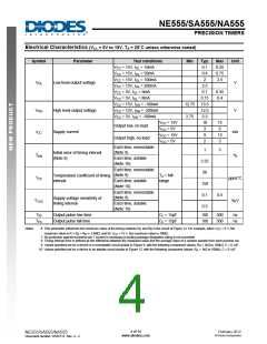
Typical Applications Characteristics (cont.)
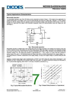
Astable Operation
As shown in Figure 4, adding a second resistor, RB, to the circuit of Figure 1 and connecting the trigger input to the threshold
input causes the timer to self-trigger and run as a multivibrator. The capacitor C charges through RA and RB and then
discharges through RB. Therefore, the duty cycle is controlled by the values of RA and RB.
This astable connection results in capacitor C charging and discharging between the threshold-voltage level (≉0.67VCC) and
the trigger-voltage level (≉0.33VCC). As in the monostable circuit, charge and discharge times (and, therefore, the frequency
and duty cycle) are independent of the supply voltage.
VCC
(5V to 15V)
0.01µF
Open
(See Note A)
RA
RL
5
8
CONT
RESET
VCC
4
7
DISCH
Output
3
OUT
RB
C
6
2
THRES
TRIG
GND
1
Decoupling CONT voltage to ground with a capacitor can
improve operation. This should be evaluated for individual
applications.
Fig. 5 Typical Astable Waveforms
Fig. 4 Circuit for Astable Operation
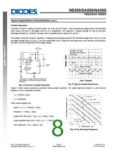
Figure 5 shows typical waveforms generated during astable operation. The output high-level duration tH and low-level
duration tL can be calculated as follows:
tH = 0.693(RA +RB)C
tL = 0.693(RB)C
Other useful equations are:
period = tH + tL = 0.693(RA + 2RB)C
frequency = 1.44/(RA + 2RB)C
output driver duty cycle = tL/(tH + tL) = RB/(RA + 2RB)
output waveform duty cycle = tH/(tH + tL) = 1 – RB/(RA + 2RB)
low to high ratio = tL/tH = RB/(RA + RB)
Fig. 6 Free Running Frequency
8 of 14
www.diodes.com
February 2012
© Diodes Incorporated
NE555/SA555/NA555
Document number: DS35112 Rev. 4 - 2
.图片预览")
 ETC [ ETC ]