TEA1716T
NXP Semiconductors
Resonant power supply control IC with PFC
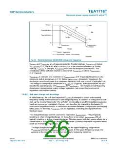
V
reg
V
Boost
V
uvp
t
GATEHS
GATELS
t
t
sink
0
sink current only with positive V
SNSCURHBC
I
SNSCURHBC
t
source
V
= R × I
cur(HBC) Cur(HBC)
Cur(HBC)
I
ocp(high)
I
ocr(high)
I
ocp(nom)
I
ocr(nom)
I
Cur(HBC)
t
0
−I
ocr(nom)
−I
ocp(nom)
−I
ocr(high)
ocp(high)
−I
V
SNSCURHBC
V
ocp(HBC)
V
ocr(HBC)
V
SNSCURHBC
0
ocr(HBC)
ocp(HBC)
t
−V
−V
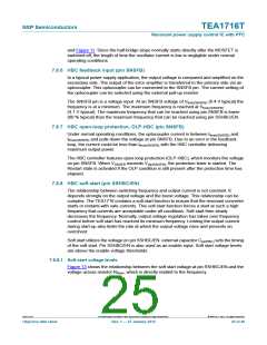
nominal V
Boost
nominal V
low V
Boost
low V
Boost
Boost
no compensation
no compensation
strong compensation
strong compensation
nominal OCR
nominal OCP
high OCR
high OCP
014aaa865
Fig 15. Boost voltage compensation
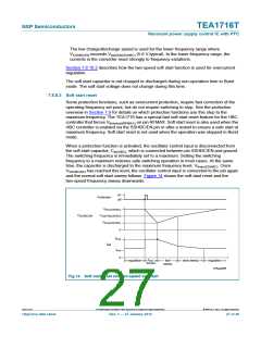
7.8.10.2 Overcurrent regulation, OCR-HBC
The lowest comparator levels at the SNSCURHBC pin, Vocr(HBC) (0.5 V and
+0.5 V typical), relate to the overcurrent regulation voltage. There are comparators for
both the positive and negative polarities. The positive comparator is active during the
high-side on-time and the following high-side to low-side non-overlap time. The negative
comparator is active during the remaining time. If either level is exceeded, the frequency
is slowly increased. Discharging the soft start capacitor accomplishes this. Each time the
OCR level is exceeded, the event is latched until the next stroke and the soft start
discharge current is enabled. When both the positive and negative OCR levels are
exceeded, the soft start discharge current flows continuously.
Overcurrent regulation is very effective at limiting the output current during start-up. A
smaller soft start capacitor can be used to achieve a faster start-up. Using a smaller
capacitor can result in an output current that is too high at times. However, the OCR
function slows down the frequency sweep when required to keep the output current within
the specified limits. Figure 16 shows the operation of the OCR during output voltage
start-up.
TEA1716T
All information provided in this document is subject to legal disclaimers.
© NXP B.V. 2012. All rights reserved.
Objective data sheet
Rev. 1 — 27 January 2012
29 of 46

 ETC [ ETC ]