SigmaTel, Inc.
Data Sheet
STAC9721
3. DIGITAL INTERFACE
3.1 AC-Link Digital Serial Interface Protocol
The STAC9721/23 communicates to the AC'97 controller via a 5-pin digital serial AC-Link interface,
which is a bi-directional, fixed rate, serial PCM digital stream. All digital audio streams, commands and
status information are communicated over this point-to-point serial interconnect. The AC-Link handles
multiple inputs, and output audio streams, as well as control register accesses using a time division
multiplexed (TDM) scheme. The AC'97 controller synchronizes all AC-Link data transaction. The
following data streams are available on the STAC9721/23:
PCM Playback
PCM Record data
Control
4 output slots
2 input slots
2 output slots
2 input slots
4 Channel composite PCM output stream
2 Channel composite PCM input stream
Control register write port
Status
Control register read port
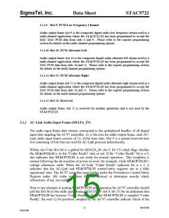
Synchronization of all AC-Link data transactions is handled by the AC'97 controller. The STAC9721/23
drives the serial bit clock onto AC-Link. The AC'97 controller then qualifies with a synchronization
signal to construct audio frames.
SYNC, fixed at 48 kHz, is derived by dividing down the serial bit clock (BIT_CLK). BIT_CLK, fixed at
12.288 MHz, provides the necessary clocking granularity to support 12, 20-bit outgoing and incoming
time slots. AC-Link serial data is transitioned on each rising edge of BIT_CLK. The receiver of AC-
Link data, STAC9721/23 for outgoing data and AC'97 controller for incoming data, samples each serial
bit on the falling edges of BIT_CLK.
The AC-Link protocol provides for a special 16-bit (13-bits defined, with 3 reserved trailing bit positions)
time slot (Slot 0) wherein each bit conveys a valid tag for its corresponding time slot within the current
audio frame. A “1” in a given bit position of slot 0 indicates that the corresponding time slot within the
current audio frame has been assigned to a data stream, and contains valid data. If a slot is “tagged”
invalid, it is the responsibility of the source of the data (STAC9721/23 for the input stream, AC'97
controller for the output stream) to stuff all bit positions with 0’s during that slot’s active time.
SYNC remains high for a total duration of 16 BIT_CLKs at the beginning of each audio frame. The
portion of the audio frame where SYNC is high is defined as the “Tag Phase”. The remainder of the
audio frame where SYNC is low is defined as the “Data Phase”.
Additionally, for power savings, all clock, sync, and data signals can be halted.
11
04/07/00
04/07/00

 ETC [ ETC ]