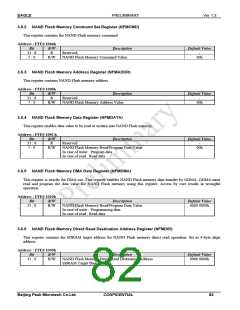
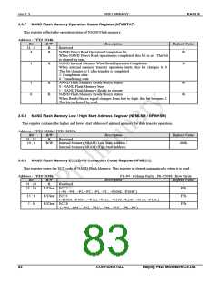
EAGLE
PRELIMINARY
Ver 1.3
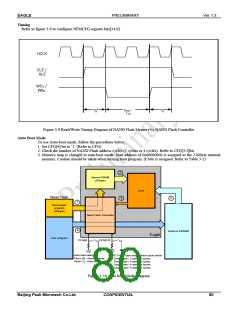
Timing
Refer to figure 3-9 to configure NFMCFG register bits[14:0].
Figure 3-9 Read/Write Timing Diagram of NAND Flash Memory by NAND Flash Controller
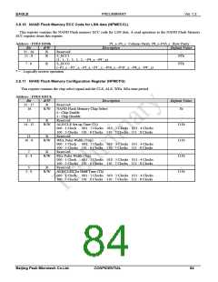
Auto Boot Mode
To use Auto-boot mode, follow the procedures below.
1. Set CFG[4] bit to ‘1’ (Refer to CFG).
2. Check the number of NAND Flash address cycles (3 cycles or 4 cycles). Refer to CFG[3:2]bit.
3. Memory map is changed to auto-boot mode. Start address of 0x00000000 is assigned to the 2-KByte internal
memory. Caution should be taken when writing boot program. (CS0x is assigned. Refer to Table 3-2)
2
Internal SRAM
(2Kbyte)
Core
Nand Flash
3
5
1
Boot loader
program
(2Kbyte)
Nand Flash Controller
4
External SDRAM
Eagle
User program
CFG[4]
CFG[3:2]
VDD
VDD
Auto load select
Close (0) : Normal mode
Open (1) : Auto boot mode
NAND Flash Type and Address cycle select
00 : Small Type / 3 address cycles
01 : Small Type / 4 address cycles
10 : Large Type / 4 address cycles
11 : Large Type / 5 address cycles
Figure 3-10 Auto boot Mode Diagram
Beijing Peak Microtech Co.Ltd.
CONFIDENTIAL
80

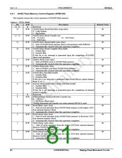
 ETC [ ETC ]