Ver 1.3
PRELIMINARY
EAGLE
3.12.4 Status and Playback Set Register Map
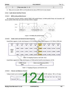
3.12.4.1 Sound Mixer Playback Set Register (SNDPLAY)
This register determines the Playback configuration.
Address: FFE0 3018h
Bit
31 : 8
7 : 4
R/W
R
R/W
Description
Default Value
Reserved
Division Factor : 0 ~ 15
Generate master clock
-
0h
master clock = AHB clock / ( division factor + 1 )
Reserved
Sound data access mode
0: DMA mode
3
2
R
R/W
-
0b
1: Polling mode (for Test mode)
1
0
R/W
R/W
Master Clock Select
0 : AHB Clock
1 : External Clock (16.9344MHz)
Sound Mixer Playback
0b
0b
0 : Playback End
1 : Playback Start (During Playback)
sampling frequency – 44.1kHz
Division Factor is used when selecting AHB Clock from Master Clock Select bit.
Sound data access mode determines the Sound data memory access. The default scheme is set as DMA mode. In AHB
Master operation, 32-bit size and 8-beat incrementing burst approach shall occur in a Single Transfer. When Sound
data access mode bit is set to ‘1’ for Test mode, the polling scheme shall fill 8 Sound data of the corresponding
channel into FIFO.
Master Clock Select bit decides whether External Clock or internal dividing clock from the AHB Clock shall be used.
The external clock requires 16.9344 MHz. While AHB clock (i.e. dividing clock from System Clock), of 16.9344
MHz is generated using appropriate Divider value.
Sound Mixer Playback bit enables the playback of Sound Mixer
3.12.5 Test Mode Register Map
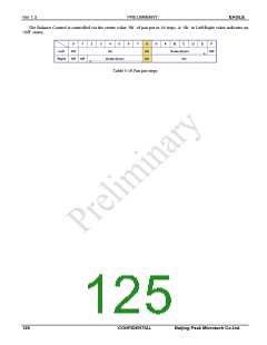
3.12.5.1 Sound Data Channel n FIFO Buffer Register (SNDBUFn)
This register is used during test mode to write a sound data into Channel FIFO.
Address: FFE0 300Ch / FFE0 302Ch / FFE0 304Ch / FFE0 306Ch / FFE0 308Ch / FFE0 30ACh / FFE0 30CCh
/ FFE0 30ECh
Bit
R/W
Description
Default Value
31 : 0
R/W
FIFO Buffer
When setting Polling mode for Test, in FIFO write possibility
0h
Each Channel FIFO is 16x32 bits.
In test mode, the channel On / Off register must be configured as ‘OFF’. In Playback mode, correct sound data will
appear if FIFO is not empty.
3.12.5.2 Sound Data Channel n FIFO Level Status Register (SNDLEVn)
This register indicates the current FIFO Level of each channel.
Address: FFE0 301Ch / FFE0 303Ch / FFE0 305Ch/ FFE0 307Ch / FFE0 309Ch / FFE0 30BCh / FFE0 30DCh / FFE0
30FCh
Bit
31 : 5
4 : 0
R/W
R
R
Description
Default Value
Reserved
FIFO Level
-
0h
123
CONFIDENTIAL
Beijing Peak Microtech Co.Ltd.

 ETC [ ETC ]