Ver 1.3
PRELIMINARY
EAGLE
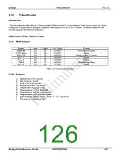
3.13.3 General Description
Video encoder is a digital encoder, comprising Color Bar Pattern Generator, RGB to YCbCr color space converter, internal
timing generator and multi-standard encoder and register block. For convenient control of images, HUE control and
Chrominance Low-Pass Filter functions are supported. Enc_HPC and Enc_VPC control registers are also supported to
control Horizontal/Vertical Active Signal Enc_HAV, Enc_VAV start position and polarity.
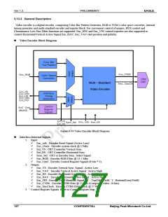
Video Encoder Block Diagram
Color Bar
Test Pattern
Enc_CVBS
Enc_RGB
Color Space
Converter
10bit
DAC
Multi- Standard
Video Encoder
Enc_ DacClk
Enc_VS
Interface
Enc_VAV
Enc_HS
Enc_HAV
Enc_FID
Timing
Generator
Control
Register
Signals
EnC Cntrl
_
(8bit*3)
Ext_VS
Ext_HS
Enc_ rstb
Enc_Clk
Sync_Sel
Figure 3-19 Video Encoder Block Diagram
Interface Internal Signals
1. Input:
9
9
9
9
9
9
9
Enc_rstb : Encoder Reset Signal (Active Low)
Enc_Clock : Encoder system clock @ 27Mhz
Ext_VS : CRT Controller Vertical Sync.
Ext_HS : CRT Controller Horizontal Sync.
Sync_Sel : CRT or Encoder Sync. Select Signal
Enc_RGB : Encoder RGB 8 bits @ 13.5 Mhz
Enc_Cntrl : Encoder Control Register Signals (8 bits * 3)
2. Output:
9
9
9
9
9
9
9
Enc_VS : Encoder Vertical Sync. Signal : Active Low
Enc_VAV : Encoder Vertical Active Signal : Active High
Enc_HS : Encoder Horizontal Sync. Signal : Active Low
Enc_HAV : Encoder Horizontal Active Signal : Active High
Enc_FID : Encoder Field Identifier Signal (‘0’ : Top(Odd) Field, ‘1’: Bottom(Even) Field)
Enc_CVBS : Encoder CVBS Data @ 27 Mhz (Composite video: 10 bits)
Enc_DacClock : Encoder CVBS DAC Clock @ 27 Mhz
3. Control Register Signals: Refer to Control Register Map
127
CONFIDENTIAL
Beijing Peak Microtech Co.Ltd.

 ETC [ ETC ]