NCP1200
3. Permanently force the V level above V
with
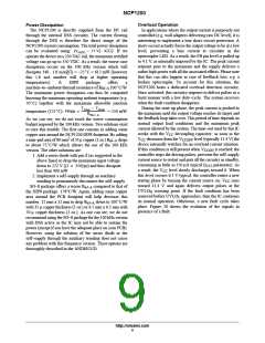
When FB is above the skip cycle threshold (1.4 V by
CC
CCH
an auxiliary winding. It will automatically
default), the peak current cannot exceed 1 V/Rsense. When
the IC enters the skip cycle mode, the peak current cannot go
below Vpin1 / 4 (Figure 19). The user still has the flexibility
to alter this 1.4 V by either shunting pin 1 to ground through
a resistor or raising it through a resistor up to the desired
level.
disconnect the internal start–up source and the IC
will be fully self–supplied from this winding.
Again, the total power drawn from the mains will
significantly decrease. Make sure the auxiliary
voltage never exceeds the 16 V limit.
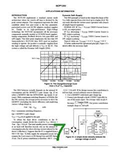
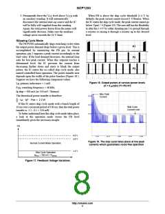
Skipping Cycle Mode
The NCP1200 automatically skips switching cycles when
the output power demand drops below a given level. This is
accomplished by monitoring the FB pin. In normal
operation, pin 2 imposes a peak current accordingly to the
load value. If the load demand decreases, the internal loop
asks for less peak current. When this setpoint reaches a
determined level, the IC prevents the current from
decreasing further down and starts to blank the output
pulses: the IC enters the so–called skip cycle mode, also
named controlled burst operation. The power transfer now
depends upon the width of the pulse bunches (Figure 18 ).
Suppose we have the following component values:
P1
P2
P3
Figure 18. Output pulses at various power levels
Lp, primary inductance = 1 mH
(X = 5 ms/div) P1<P2<P3
F , switching frequency = 48 kHz
SW
Ip skip = 300 mA (or 350 mV / Rsense)
Max Peak
Current
The theoretical power transfer is therefore:
1
2
@ Lp @ Ip2 @ Fsw + 2.2 W
If this IC enters skip cycle mode with a bunch length of
Skip Cycle
Current Limit
10 ms over a recurrent period of 100 ms, then the total power
transfer is: 2.2 . 0.1 = 220 mW.
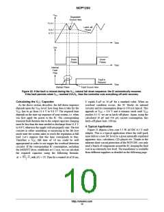
To better understand how this skip cycle mode takes place,
a look at the operation mode versus the FB level
immediately gives the necessary insight:
FB
4.8 V
3.8 V
Figure 19. The skip cycle takes place at low peak
currents which guarantees noise free operation
Normal Current Mode Operation
1.4 V
Skip Cycle Operation
Ip
min
= 350 mV / R
sense
Figure 17. Feedback Voltage Variations
http://onsemi.com
8

 ETC [ ETC ]