NCP1200
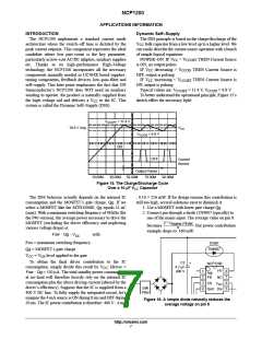
V
CC
Regulation
Occurs Here
11.4 V
Latch–off
Phase
9.8 V
6.3 V
Time
Drv
Driver
Driver
Pulses
Pulses
Time
Time
Internal
Fault
Flag
Fault is
Relaxed
Startup Phase
Fault Occurs Here
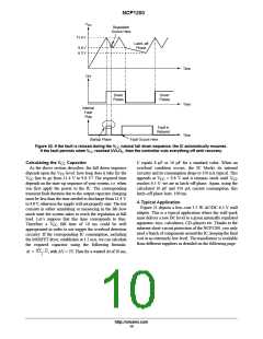
Figure 20. If the fault is relaxed during the VCC natural fall down sequence, the IC automatically resumes.
If the fault persists when VCC reached UVLOL, then the controller cuts everything off until recovery.
Calculating the V Capacitor
As the above section describes, the fall down sequence
C equals 8 µF or 10 µF for a standard value. When an
overload condition occurs, the IC blocks its internal
circuitry and its consumption drops to 350 µA typical. This
CC
depends upon the V level: how long does it take for the
CC
V
CC
line to go from 11.4 V to 9.8 V? The required time
appends at V = 9.8 V and it remains stuck until V
CC CC
depends on the start–up sequence of your system, i.e. when
you first apply the power to the IC. The corresponding
transient fault duration due to the output capacitor charging
must be less than the time needed to discharge from 11.4 V
to 9.8 V, otherwise the supply will not properly start. The test
consists in either simulating or measuring in the lab how
much time the system takes to reach the regulation at full
load. Let’s suppose that this time corresponds to 6ms.
reaches 6.5 V: we are in latch–off phase. Again, using the
calculated 10 µF and 350 µA current consumption, this
latch–off phase lasts: 109 ms.
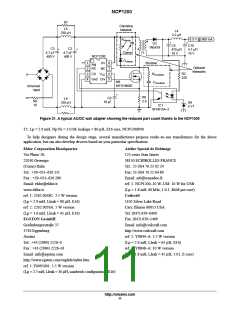
A Typical Application
Figure 21 depicts a low–cost 3.5 W AC/DC 6.5 V wall
adapter. This is a typical application where the wall–pack
must deliver a raw DC level to a given internally regulated
apparatus: toys, calculators, CD–players etc. Thanks to the
inherent short–circuit protection of the NCP1200, you only
need a bunch of components around the IC, keeping the final
cost at an extremely low level. The transformer is available
from different suppliers as detailed on the following page.
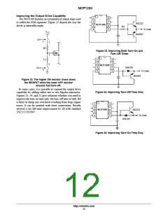
Therefore a V
fall time of 10 ms could be well
CC
appropriated in order to not trigger the overload detection
circuitry. If the corresponding IC consumption, including
the MOSFET drive, establishes at 1.5 mA, we can calculate
the required capacitor using the following formula:
DV @ C
Dt +
, with DV = 2V. Then for a wanted Dt of 10 ms,
i
http://onsemi.com
10

 ETC [ ETC ]