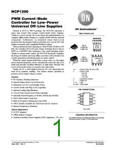
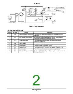
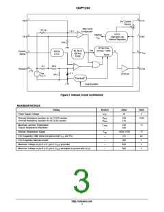
NCP1200
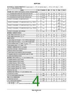
ELECTRICAL CHARACTERISTICS (For typical values T = +25°C, for min/max values T = –25°C to +125°C, Max T = 150°C,
J
J
J
V
CC
= 11 V unless otherwise noted)
Rating
DYNAMIC SELF–SUPPLY (All frequency versions, otherwise noted)
Pin
Symbol
Min
Typ
Max
Unit
V
V
V
increasing level at which the current source turns–off
decreasing level at which the current source turns–on
decreasing level at which the latch–off phase ends
6
6
6
6
V
10.3
8.8
–
11.4
9.8
12.5
11
V
V
CC
CC
CC
CCOFF
V
CCON
V
6.3
–
V
CClatch
Internal IC Consumption, no output load on pin 6
Internal IC Consumption, 1 nF output load on pin 6, F
Internal IC Consumption, 1 nF output load on pin 6, F
Internal IC Consumption, 1 nF output load on pin 6, F
I
I
I
I
I
–
710
880
Note 1
µA
CC1
CC2
CC2
CC2
CC3
= 40 kHz
= 60 kHz
= 100 kHz
6
6
6
6
–
–
–
–
1.2
1.4
1.9
350
1.4
Note 2
mA
mA
mA
µA
SW
SW
SW
1.6
Note 2
2.2
Note 2
Internal IC Consumption, latch–off phase
–
INTERNAL CURRENT SOURCE
High–voltage current source, V = 10 V
8
8
I
I
2.8
–
4.0
4.9
–
–
mA
mA
CC
C1
High–voltage current source, V = 0
CC
C2
DRIVE OUTPUT
Output voltage rise–time @ CL = 1 nF, 10–90% of output signal
Output voltage fall–time @ CL = 1 nF, 10–90% of output signal
5
5
5
5
T
–
–
67
28
40
12
–
–
ns
ns
W
r
T
f
Source resistance (drive = 0, Vgate = V
– 1 V)
R
27
5
61
20
CCHMAX
OH
Sink resistance (drive = 11 V, Vgate = 1 V)
CURRENT COMPARATOR (Pin 5 un–loaded)
Input Bias Current @ 1 V input level on pin 3
Maximum internal current setpoint
R
W
OL
3
3
3
3
3
I
IB
–
0.8
–
0.02
0.9
–
1.0
–
µA
V
I
Limit
Default internal current setpoint for skip cycle operation
Propagation delay from current detection to gate OFF state
Leading Edge Blanking Duration
I
350
100
230
mV
ns
ns
Lskip
T
–
160
–
DEL
LEB
T
–
INTERNAL OSCILLATOR (V = 11 V, pin 5 loaded by 1 kW)
CC
Oscillation frequency, 40 kHz version
Oscillation frequency, 60 kHz version
Oscillation frequency, 100 kHz version
–
–
–
–
–
–
–
f
f
f
36
52
86
–
42
61
48
70
116
–
kHz
kHz
kHz
Hz/V
Hz/V
Hz/V
%
OSC
OSC
OSC
103
300
450
620
80
Built–in frequency jittering, F
Built–in frequency jittering, F
Built–in frequency jittering, F
Maximum duty–cycle
= 40 kHz
= 60 kHz
= 100 kHz
f
SW
SW
SW
jitter
jitter
jitter
f
–
–
f
–
–
Dmax
74
87
FEEDBACK SECTION (Vcc = 11 V, pin 5 loaded by 1 kW)
Internal pull–up resistor
2
–
Rup
–
–
8.0
4.0
–
–
kW
Pin 3 to current setpoint division ratio
SKIP CYCLE GENERATION
Iratio
–
Default skip mode level
1
1
Vskip
Zout
1.1
–
1.4
25
1.6
–
V
Pin 1 internal output impedance
kW
1. Max value @ T = –25°C.
J
2. Max value @ T = 25°C, please see characterization curves.
J
http://onsemi.com
4

 ETC [ ETC ]