1-2-1 2-Phase Stepper Motor Unipolar Driver ICs
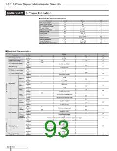
SMA7036M 2-Phase Excitation
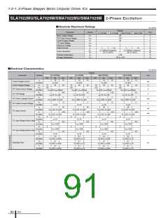
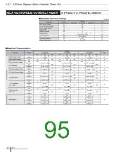
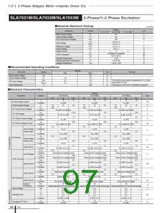
■Absolute Maximum Ratings
Parameter
Motor Supply Voltage
Control Supply Voltage
FET Drain-Source Voltage
TTL Input Voltage
Symbol
Ratings
46
Unit
V
V
CC
VS
46
V
V
DSS
IN
SYNC
REF
100
V
V
–0.3 to +7
–0.3 to +7
–0.3 to +7
–5 to +7
1.5
V
SYNC Terminal Voltage
Reference Voltage
Sense Voltage
V
V
V
V
V
RS
V
Output Current
I
O
A
P
P
D1
D2
4.0 (T
28 (T
150
a
=25°C)
W
W
Power Dissipation
c=25°C)
Channel Temperature
T
ch
°C
°C
°C
Storage Temperature
Tstg
–40 to +150
–20 to +85
Operating Ambient Temperature
Ta
■Electrical Characteristics
Ratings
typ.
Parameter
Symbol
Unit
min.
max.
I
S
10
15
Control Supply Current
Control Supply Voltage
FET Drain-Source Voltage
mA
V
Condition
VS
=44V
24
V
S
10
44
VDSS
100
V
Condition
VS=44V, IDSS=250µA
V
DS
0.6
1.1
250
FET ON Voltage
V
V
Condition
ID=1A, VS=10V
VSD
FET Diode Forward Voltage
FET Drain Leakage Current
Condition
ISD=1A
I
DSS
µA
Condition
VDSS=100V, VS=44V
V
IH
2
2
Condition
ID=1A
Active H
V
V
IL
0.8
Condition
V
DSS=100V
DSS=100V
VIH
IN Terminal
Active L
Condition
V
V
µA
V
V
IL
0.8
Condition
ID=1A
Input
Current
I
I
±1
Condition
VS=44V, VI=0 or 5V
VSYNC
H
4.0
Condition
Synchronous chopping mode
Asynchronous chopping mode
Input
Loltage
VSYNC
L
0.8
0.1
–0.1
2.0
5.5
±1
Condition
SYNC Terminal
I
SYNCH
Input
Current
Condition
V
V
S
=44V, VYS=5V
=44V, VYS=0V
mA
V
I
SYNCL
Condition
S
V
REF
0
Input
Voltage
Condition
Reference voltage input
Output FET OFF
V
REF
4.0
Condition
REF Terminal
Input
I
REF
µA
Current
Condition
No synchronous trigger
40
RREF
Internal
Resistance
Ω
Condition
Resistance between GND and REF terminal at synchronous trigger
1.5
Ton
Condition
VS
VS
VS
VS
=24V, I
D=1A
D=1A
D=1A
D=1A
Tr
0.5
Condition
=24V, I
0.9
µs
µs
Switching Time
Tstg
Condition
=24V, I
0.1
Tf
Condition
=24V, I
12
TOFF
Chopping OFF Time
Condition
VS=24V
ICs
92

 ETC [ ETC ]