SI-3000KWM Series
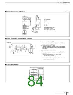
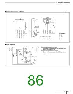
■External Dimensions (TO252-5)
(Unit : mm)
6.60±0.20
5.34±0.20
(5.04)
2.30±0.20
6.60±0.20
5.34±0.20
0.50±0.10
(1.50)
SEATING PLANE
0.00 to 0.127
0.1
°
Pin Assignment
q VC
0
to 8
0.50±0.10
(1.00)
0.50±0.10
w VO1
1.27 TYP
1.27 TYP
2.30±0.20
Plastic Mold Package Type
Flammability: UL 94V-0
e GND
r VIN
1
2
3
4
5
Product Mass: Approx. 1.48 g
t VO2
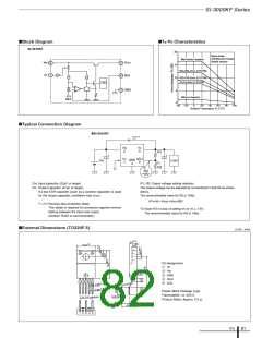
■Block Diagram
V
IN
VOUT1
CIN: Input capacitor (Approx. 0.1 to 10µF)
This capacitor is required when the input line contains induc-
tance or when the wiring is long.
4
2
+
C
IN
Co1, Co2: Output capacitor (22µF or higher)
The output voltage may oscillate if a low ESR type capacitor
(such as a ceramic capacitor) is used for the output capacitor
in SI-3000KWM.
Drive
OCP
+
–
REF
+
COUT1
AMP2
ON/
+ TSD
–
VC
OFF
–
1
+
VOUT2
5
+
Drive
OCP
C
OUT2
+
–
AMP2
GND
3
ICs
85

 ETC [ ETC ]