SI-3000ZF Series
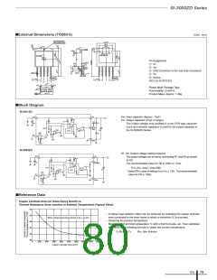
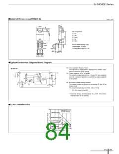
■External Dimensions (TO220F-5)
(unit : mm)
0.2
4.2
2.8
0.2
0.2
10.0
φ
Pin Assignment
q VC
w VIN
e GND
r Vo
0.1
2.6
t ADJ
0.15
0.95
0.85
Plastic Mold Package Type
Flammability: UL94V-0
+0.2
–0.1
+0.2
–0.1
Product Mass: Approx. 2.3g
0.7
P1.7 0.7×4=6.8
0.45
0.7
(4.3)
0.7
3.9
8.2
1
2 3 4 5
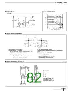
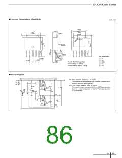
■Typical Connection Diagram/Block Diagram
CIN: Input capacitor (Approx. 10µF)
SI-3011ZF
This capacitor is required when the input line contains induc-
tance or when the wiring is long.
V
IN
V
O
2
4
5
CO: Output capacitor (47µF or higher)
+
*
R3
The output voltage may oscillate if a low ESR type capacitor
(such as a ceramic capacitor) is used for the output capacitor
in SI-3000ZF.
R1
C
IN
+
+
-
Drive
OCP
REF
ADJ
TSD
CO
AMP1
+
ON/
OFF
-
R2
V
C
R1, R2: Output voltage setting resistors
The output voltage can be set by connecting R1 and R2 as
shown at left.
1
-
+
3
GND
The recommended value for R2 is 10kΩ or 11kΩ.
R1= (VO–VADJ) / (VADJ/R2)
*: Insert R3 in case of setting VO to VO ≤ 1.8V. The recom-
mended value for R3 is 10kΩ.
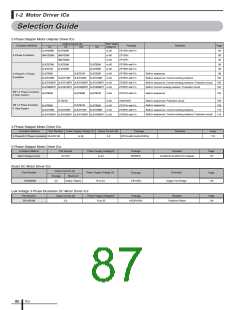
■Ta-PD Characteristics
25
20
15
10
5
With Silicone Grease
Heatsink: Aluminum
With Infinite Heatsink
200×200×2mm (2.3°C/W)
100×100×2mm (5.2°C/W)
75×75×2mm (7.6°C/W)
Without heatsink
0
–30
0
25
50
75
100
Ambient Temperature T
a
(°C)
ICs
83

 ETC [ ETC ]