1-2-6 High Voltage 3-Phase Brushless Motor Driver ICs
SCM1200M Series IGBT Output Element, Built-in Thermal Shutdown, Overcurrent Protection, and Shoot Through Prevention Circuits
■Features
• Six IGBTs and six FRDs for the 3-phase bridge, a pre-drive IC, and a boot diode are integrated into a single package
• Ideal for driving air conditioner compressors, washing machine drums, and refrigerator compressors
• Built-in shoot through prevention (STP) circuit (when the ON signal is input simultaneously)
• All IGBTs can be shut down when commonly connected to the FO pin.
• Three built-in bootstrap diodes
• Supports CMOS (3.3 and 5 V) input levels
• Built-in undervoltage lock out (UVLO) circuit (auto regression)
• Built-in overcurrent protection (OCP) circuit
• Built-in thermal shut down (TSD) circuit (auto regression)
• Fail signal output during operation of the UVLO (low side only), OCP, or STP circuit
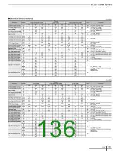
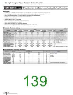
■Absolute Maximum Ratings
(T a=25℃)
a
(T =25℃)
Ratings
Parameter
Symbol
S1221M
(SCM1221MF)
450
SCM1223M
SCM1224M
(SCM1224MF)
SCM1225MF
SCM1226M
(SCM1226MF)
450
SCM1230MF
Unit
Conditions
Supply Voltage
VDC
450
500
600
20
20
5
10
450
500
600
20
20
450
500
600
20
20
15
30
450
500
600
20
20
15
30
V
V
V
V
V
A
A
V
V
W
Between VBB and LS1 to LS3
Between VBB and LS1 to LS3
VCC=15V,IC=1mA,VIN=0V
Between VCC and COM
Between VB and HS (U, V, W)
Supply Voltage (Surge)
IGBT Output Breakdown Voltage
Control Supply Voltage
Control Supply Voltage (Bootstrap)
Output Current (continuous)
Output Current (pulse)
Input Voltage
FO Pin Voltage
Collector Dissipation
Thermal Resistance
(Junction to Case)
V
DC(Surge)
VCES
VCC
VBS
Io
500
600
20
20
10
20
500
600
20
20
10
20
8
16
Tc=25℃
PW<1ms
Iop
VIN
–0.5 to +7
7
–0.5 to +7
7
19.8
6.3
6.5
–20 to +100
150
–40 to +150
2000
–0.5 to +7
7
–0.5 to +7
7
41.6
3.0
4.0
–20 to +100
150
–40 to +150
2000
–0.5 to +7
7
–0.5 to +7
7
41.6
3.0
4.0
–20 to +100
150
–40 to +150
2000
HIN,LIN,OCP
VFO
PD
Between FO and COM
TC=25℃, per IGBT element
20.8(33.7)
6.0(3.7)
6.5(4.2)
–20 to +100
150
20.1(32.8)
6.2(3.8)
6.5(4.2)
–20 to +100
150
20.8(33.7)
6.0(3.7)
6.5(4.2)
–20 to +100
150
R(j-c)Q
R(j-c)F
COP
Tj
℃/W Per IGBT element
℃/W Per FWD element
℃
℃
Operating Case Temperature
Junction Temperature (Power part)
Storage Temperature
Tstg
Viso
–40 to +150
2000
–40 to +150
2000
–40 to +150
2000
°C
Insulation Breakdown Voltage
Vrms Between rear and lead pins, AC one minute
■Recommended Operating Conditions
Ratings
Parameter
Symbol
SCM1200M Series
Unit
Conditions
min.
-
typ.
300
-
max.
400
16.5
-
Main Supply Voltage
Control Supply Voltage
VDC
V
V
Between VBB and LS
VCC,VBS
tINmin(on)
13.5
0.5
0.5
1.0
1
1
4.5
10
-
µs
µs
µs
kΩ
nF
V
uF
kHz
℃
ON pulse
Minimum Input Pulse Width
tINmin(off)
tdead
RFO
CFO
VFO
CBOOT
fc
-
-
-
-
-
-
-
-
-
-
22
10
5.5
220
20
OFF pulse
Input Signal Dead Time
FO Pull-up Resistance
CFO Capacitor Capacity
FO Pull-up Voltage
Boot Capacitor
PWM Carrier Frequency
Junction Temperature
-
-
For the SCM1221M (F) and SCM1225MF: 10
Tj
125
ICs
138

 ETC [ ETC ]