7#0#7#(OHFWULFDO#,QVWDOODWLRQ
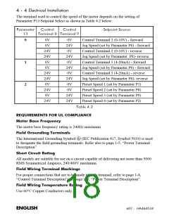
The terminal used to control the speed of the motor depends on the setting of
Parameter P13 Setpoint Select as shown in Table 4.2 below:
3DUDPHWHU
&RQWURO
&RQWURO
6HWSRLQW#6RXUFH
46
7HUPLQDO#; 7HUPLQDO#<
0V
0V
0V
24V
0V
Control Terminal 2 (0-10V) - forward
Jog Speed (set by Parameter P8) - forward
Control Terminal 2 (0-10V) - reverse
Jog Speed (set by Parameter P8)- reverse
Control Terminal 3 (4-20mA) - forward
Jog Speed (set by Parameter P8) - forward
Control Terminal 3 (4-20mA) - reverse
Jog Speed (set by Parameter P8)- reverse
Preset Speed 1 (set by Parameter P1)
Preset Speed 2 (set by Parameter P8)
Preset Speed 3 (set by Parameter P9)
Preset Speed 4 (set by Parameter P2)
0
1
2
24V
24V
0V
24V
0V
0V
24V
0V
24V
24V
0V
24V
0V
24V
0V
0V
24V
24V
24V
7DEOH#715
5(48,5(0(176#)25#8/#&203/,$1&(
0RWRU#%DVH#)UHTXHQF\
The motor base frequency rating is 240Hz maximum
)LHOG#*URXQGLQJ#7HUPLQDOV
The International Grounding Symbol
(IEC Publication 417, Symbol 5019) is used
to designate the field grounding terminals. Refer also to page 1-5, “Power Terminal
Description”
6KRUW#&LUFXLW#5DWLQJ
All models are suitable for use on a circuit capable of delivering not more than 5000
RMS Symmetrical Amperes, 240/460V maximum.
)LHOG#:LULQJ#7HUPLQDO#0DUNLQJV
For proper connections that are to be made to each terminal, refer to page 1-4,
“Control Terminal Description” and page 1-5, “Power Terminal Description”.
)LHOG#:LULQJ#7HPSHUDWXUH#5DWLQJ
Use 60°C Copper Conductors only.
(1*/,6+
934#0##+$79784;

 ETC [ ETC ]