7#0#9#(OHFWULFDO#,QVWDOODWLRQ
NOTE: THE DYNAMIC BRAKING CIRCUIT IS DESIGNED TO COPE
WITH SHORT TERM STOPPING OR BRAKING ONLY.
IT IS NOT RATED FOR A CONTINUOUSLY OVERHAULING LOAD.
All 601 units are supplied without braking resistors. The following paragraphs
should be used as a guide to calculate the braking requirements of the system.
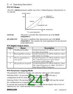
%UDNH#5HVLVWRU#6HOHFWLRQ
Brake resistor assemblies must be rated to absorb both peak braking power during
deceleration and the average power over the complete cycle.
2
2
2
J
- total inertia (kgm )
0.0055J x (n1 - n2 )
(W)
Peak braking power =
n - initial speed (rpm)
t
1
b
n - final speed (rpm)
2
p
pk
t
t
- braking time (s)
- cycle time (s)
b
c
x t
Average braking power P =
b
av
t
c
flying leads 500 mm
152 mm
22 mm
10 mm
4.3mm
45#PP
12 mm
10 mm
458#PP
41 mm
498#PP
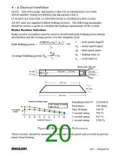
Eurotherm Part No CZ389853
Resistor Derating Graph
chassis mounted
free air
Resistance
100 ohms
100 W
10
Max Wattage
5 second rating
3 second rating
1 second rating
% of Rated
50
Power
500 %
0
833 %
0
25
50
75
10
12
15
17
20
Ambient Temp (C)
2500 %
)LJXUH#719#%UDNLQJ#5HVLVWRU#3HUIRUPDQFH
These resistors should be mounted on a heatsink (back panel) and covered to prevent
injury from burning.
(1*/,6+
934#0##+$79784;

 ETC [ ETC ]