EXTERNAL
REF
LO HI
R
R
R
1
.
4
R
3
RL RH
See Note 3ꢀ
+S
-S
S3
S1
SIN
COS
-C
+C
See Note 3ꢀ
S.
S4
A GND
GND
RESOLVER
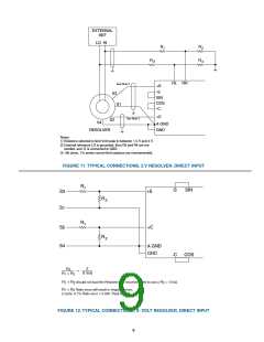
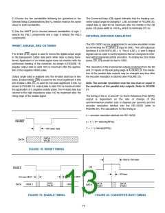
Notes:
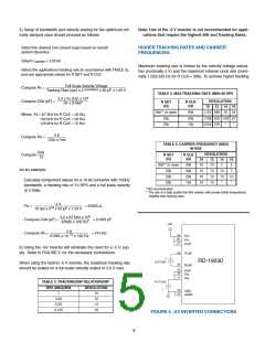
1) Resistors selected to limit Vref peak to between 1ꢀ5 V and 4 Vꢀ
.) External reference LO is grounded, then R3 and R4 are not
needed, and -R is connected to GNDꢀ
3) 10k ohms, 1% series current limit resistors are recommendedꢀ
FIGURE 11. TYPICAL CONNECTIONS, 2 V RESOLVER, DIRECT INPUT
R
1
-S
SIN
S3
S1
+S
R
R
.
R
1
S.
S4
+C
.
A GND
GND
-C
COS
.
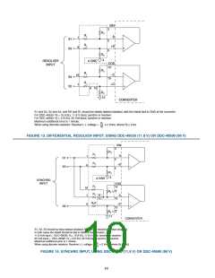
R
.
=
X Volt
R + R
1
.
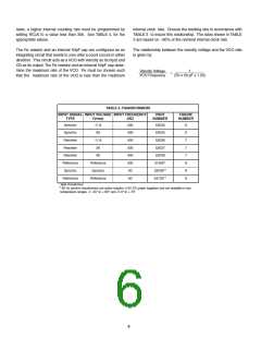
R + R should not load the Resolver; it is recommended to use a R = 10 kΩ
1
.
.
R + R Ratio erros will result in Angular errors,
1
.
. cycle, 0ꢀ1% Ratio error = 0ꢀ0.9 Peak Errorꢀ
FIGURE 12. TYPICAL CONNECTIONS, X- VOLT RESOLVER, DIRECT INPUT
9

 ETC [ ETC ]