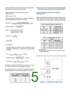
rates, a higher internal counting rate must be programmed by
setting RCLK to a value less than 30kꢀ See TABLE 4ꢀ for the
appropriate valuesꢀ
internal clock rateꢀ Choose the tracking rate in accordance with
TABLE 3 to insure this relationshipꢀ The rates shown in TABLE
3 are based on ~90% of the nominal internal clock rateꢀ
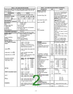
The Rv resistor and an internal 50pF cap are configured as an
integrating circuit that resets to zero after a count occurs in either
directionꢀ This circuit acts as a VCO with velocity as its input and
CB as its outputꢀThe Rv resistor and an internal 50pF cap deter-
mine the maximum rate of the VCOꢀ Rv must be chosen such
that the maximum rate of the VCO is less than the maximum
The relationship between the velocity voltage and the VCO rate
is given by:
1
Velocity Voltage
VCO Frequency
=
(Rv x 50 pF x 1ꢀ.5)
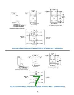
TABLE 5. TRANSFORMERS
INPUT SIGNAL INPUT VOLTAGE INPUT FREQUENCY
PART
FIGURE
TYPE
(Vrms)
(HZ)
NUMBER
NUMBER
Synchro
11ꢀ8
400
5.034
5.035
5.036
5.037
5.038
B-4.6*
5.039**
.4133**
6
6
7
7
7
8
9
9
Synchro
Resolver
Resolver
Resolver
Reference
Synchro
90
11ꢀ8
400
400
400
400
400
60
.6
90
Reference
Synchro
Reference
Reference
60
* Beta Transformer
** 60 Hz synchro transformers are active (require 15V DC power supplies) and are available in two
temperature ranges; -1: -55° to +1.5° and -3: 0° to + 70°ꢀ
6

 ETC [ ETC ]