ICL8052A/ICL71C03, ICL8068A/ICL71C03
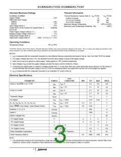
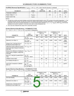
Absolute Maximum Ratings
Thermal Information
o
o
ICL8052A, ICL8068A
Thermal Resistance (Typical, Note 5)
θ
( C/W)
θ
( C/W)
JA
JC
Supply Voltage. . . . . . . . . . . . . . . . . . . . . . . . . . . . . . . . . . . . . 18V
Differential Input Voltage
CERDIP Package. . . . . . . . . . . . . . . . .
14 Ld PDIP Package . . . . . . . . . . . . . .
28 Ld PDIP Package . . . . . . . . . . . . . .
Maximum Storage Temperature. . . . . . . . . . . . . . . . -65 C to 150 C
Maximum Lead Temperature (Soldering, 10s). . . . . . . . . . . . .300 C
75
100
65
20
N/A
N/A
o
(8068A). . . . . . . . . . . . . . . . . . . . . . . . . . . . . . . . . . . . . . . . . 30V
(8052A). . . . . . . . . . . . . . . . . . . . . . . . . . . . . . . . . . . . . . . . . . 6V
Input Voltage (Note 1) . . . . . . . . . . . . . . . . . . . . . . . . . . . . . . . 15V
Output Short Circuit Duration All Outputs (Note 2) . . . . . . Indefinite
ICL71C03
o
o
Power Supply Voltage (GND to V+). . . . . . . . . . . . . . . . . . . . . . 6.5V
Negative Supply Voltage (GND to V-) . . . . . . . . . . . . . . . . . . . . -17V
Analog Input Voltage (Note 3) . . . . . . . . . . . . . . . . . . . . . . . V+ to V-
Digital Input Voltage (Note 4) . . . . . . . . .(GND - 0.3V) to (V+ + 0.3V)
Operating Conditions
o
o
Temperature Range . . . . . . . . . . . . . . . . . . . . . . . . . . . . 0 C to 70 C
CAUTION: Stresses above those listed in “Absolute Maximum Ratings” may cause permanent damage to the device. This is a stress only rating and operation of the
device at these or any other conditions above those indicated in the operational sections of this specification is not implied.
NOTES:
1. θ is measured with the component mounted on a low effective thermal conductivity test board in free air. See Tech Brief TB379 for details.
JA
2. For supply voltages less than 15V, the absolute maximum input voltage is equal to the supply voltage.
o
3. Short circuit may be to ground or either supply. Rating applies to 70 C ambient temperature.
4. Input voltages may exceed the supply voltages provided the input current is limited to 100µA.
5. Connecting any digital inputs or outputs to voltages greater then V+ or less than GND may cause destructive device latchup. For this reason it
is recommended that the power supply to the ICL71C03 be established before any inputs from sources not on that supply are applied.
6. θ is measured with the component mounted on an evaluation PC board in free air.
JA
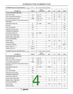
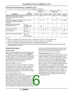
Electrical Specifications
TEST
PARAMETER
SYMBOL
CONDITIONS
MIN
TYP
0.2
0.1
0.1
0.1
2.5
0.25
4.2
4.99
400
1200
2
MAX
UNITS
mA
µA
µA
µA
V
Clock In, Run/Hold, 4 1/2 / 3 1/2
I
V
V
V
V
= 0
-
0.6
INL
IN
IN
IN
IN
I
= +5V
= 0
-
10
INH
Comp. In Current
I
-
10
INL
I
= +5V
-
10
INH
Threshold Voltage
All Outputs
V
-
-
-
INTH
V
I
I
I
= 1.6mA
= -1mA
= -10µA
0.40
V
OL
OH
OH
OL
OH
OH
B , B , B , B , D , D , D , D , D
5
V
2.4
4.9
-
-
V
1
2
4
8
1
2
3
4
Busy, Strobe, Over-Range, Under-Range Polarity
Switches 1, 3, 4, 5, 6
Switch 2
V
-
V
r
r
-
Ω
DS(ON)
DS(ON)
-
-
Ω
Switch Leakage (All)
+5V Supply Range
I
-
-
6
pA
V
D(OFF)
V+
4
5
-15V Supply Range
V-
I+
I-
-5
-
-15
1.1
0.8
40
-18
3
V
+5V Supply Current
f
f
= 0
= 0
mA
mA
pF
kHz
CLK
CLK
-15V Supply Current
Power Dissipation Capacitance
Clock Frequency (Note 6)
NOTE:
-
3
C
vs Clock Frequency
-
-
PD
DC
2000
1200
7. This specification relates to the clock frequency range over which the ICL71C03A will correctly perform its various functions. See the “Max Clock
Frequency” section under Component Value Selection for limitations on the clock frequency range in a system.
3

 ETC [ ETC ]