ST90158 - MULTIFUNCTION TIMER (MFT)
MULTIFUNCTION TIMER (Cont’d)
9.3.5 Interrupt and DMA
The two DMA End of Block interrupts are inde-
pendently enabled by the CP0I and CM0I Interrupt
mask bits in the IDMR register.
9.3.5.1 Timer Interrupt
The timer has 5 different Interrupt sources, be-
longing to 3 independent groups, which are as-
signed to the following Interrupt vectors:
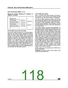
9.3.5.3 DMA Pointers
The 6 programmable most significant bits of the
DMA Counter Pointer Register (DCPR) and of the
DMA Address Pointer Register (DAPR) are com-
mon to both channels (Comp0 and Capt0). The
Comp0 and Capt0 Address Pointers are mapped
as a pair in the Register File, as are the Comp0
and Capt0 DMA Counter pair.
Table 23. Timer Interrupt Structure
Interrupt Source
Vector Address
COMP 0
COMP 1
xxxx x110
CAPT 0
CAPT 1
xxxx x100
xxxx x000
In order to specify either the Capt0 or the Comp0
pointers, according to the channel being serviced,
the Timer resets address bit 1 for CAPT0 and sets
it for COMP0, when the D0 bit in the DCPR regis-
ter is equal to zero (Word address in Register
File). In this case (transfers between peripheral
registers and memory), the pointers are split into
two groups of adjacent Address and Counter pairs
respectively.
Overflow/Underflow
The three least significant bits of the vector pointer
address represent the relative priority assigned to
each group, where 000 represents the highest pri-
ority level. These relative priorities are fixed by
hardware, according to the source which gener-
ates the interrupt request. The 5 most significant
bits represent the general priority and are pro-
grammed by the user in the Interrupt Vector Reg-
ister (T_IVR).
For peripheral register to register transfers (select-
ed by programming “1” into bit 0 of the DCPR reg-
ister), only one pair of pointers is required, and the
pointers are mapped into one group of adjacent
positions.
Each source can be masked by a dedicated bit in
the Interrupt/DMA Mask Register (IDMR) of each
timer, as well as by a global mask enable bit (ID-
MR.7) which masks all interrupts.
The DMA Address Pointer Register (DAPR) is not
used in this case, but must be considered re-
served.
If an interrupt request (CM0 or CP0) is present be-
fore the corresponding pending bit is reset, an
overrun condition occurs. This condition is flagged
in two dedicated overrun bits, relating to the
Comp0 and Capt0 sources, in the Timer Flag Reg-
ister (T_FLAGR).
Figure 62. Pointer Mapping for Transfers
between Registers and Memory
9.3.5.2 Timer DMA
Register File
Two Independent DMA channels, associated with
Comp0 and Capt0 respectively, allow DMA trans-
fers from Register File or Memory to the Comp0
Register, and from the Capt0 Register to Register
File or Memory). If DMA is enabled, the Capt0 and
Comp0 interrupts are generated by the corre-
sponding DMA End of Block event. Their priority is
set by hardware as follows:
YYYYYY11(l)
YYYYYY10(h)
YYYYYY01(l)
YYYYYY00(h)
Address
Pointers
Comp0 16 bit
Addr Pointer
Capt0 16 bit
Addr Pointer
XXXXXX11(l)
XXXXXX10(h)
XXXXXX01(l)
XXXXXX00(h)
DMA
Counters
Comp0 DMA
16 bit Counter
– Compare 0 Destination
– Capture 0 Source
—
Lower Priority
—
Higher Priority
Capt0 DMA
16 bit Counter
The two DMA request sources are independently
maskable by the CP0D and CM0D DMA Mask bits
in the IDMR register.
117/199
9

 ETC [ ETC ]