ST72104G, ST72215G, ST72216G, ST72254G
16-BIT TIMER (Cont’d)
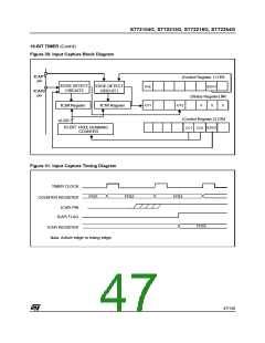
12.2.3.3 Input Capture
When an input capture occurs:
In this section, the index, i, may be 1 or 2 because
there are 2 input capture functions in the 16-bit
timer.
– The ICFi bit is set.
– The ICiR register contains the value of the free
running counter on the active transition on the
ICAPi pin (see Figure 31).
The two input capture 16-bit registers (IC1R and
IC2R) are used to latch the value of the free run-
ning counter after a transition is detected by the
ICAPi pin (see figure 5).
– A timer interrupt is generated if the ICIE bit is set
and the I bit is cleared in the CC register. Other-
wise, the interrupt remains pending until both
conditions become true.
MS Byte
ICiHR
LS Byte
ICiLR
ICiR
Clearing the Input Capture interrupt request (i.e.
clearing the ICFi bit) is done in two steps:
The ICiR register is a read-only register.
1. Reading the SR register while the ICFi bit is set.
2. An access (read or write) to the ICiLR register.
The active transition is software programmable
through the IEDGi bit of Control Registers (CRi).
Timing resolution is one count of the free running
Notes:
counter: (f
/CC[1:0]).
CPU
1. After reading the ICiHR register, the transfer of
input capture data is inhibited and ICFi will
never be set until the ICiLR register is also
read.
Procedure:
To use the input capture function, select the fol-
lowing in the CR2 register:
2. The ICiR register contains the free running
counter value which corresponds to the most
recent input capture.
– Select the timer clock (CC[1:0]) (see Table 13
Clock Control Bits).
3. The 2 input capture functions can be used
together even if the timer also uses the 2 output
compare functions.
– Select the edge of the active transition on the
ICAP2 pin with the IEDG2 bit (the ICAP2 pin
must be configured as a floating input).
4. In One Pulse mode and PWM mode only the
input capture 2 function can be used.
And select the following in the CR1 register:
– Set the ICIE bit to generate an interrupt after an
input capture coming from either the ICAP1 pin
or the ICAP2 pin
5. The alternate inputs (ICAP1 & ICAP2) are
always directly connected to the timer. So any
transitions on these pins activate the input cap-
ture function.
– Select the edge of the active transition on the
ICAP1 pin with the IEDG1 bit (the ICAP1pin must
be configured as a floating input).
Moreover if one of the ICAPi pin is configured
as an input and the second one as an output,
an interrupt can be generated if the user tog-
gles the output pin and if the ICIE bit is set.
This can be avoided if the input capture func-
tion i is disabled by reading the ICiHR (see note
1).
6. The TOF bit can be used with an interrupt in
order to measure events that exceed the timer
range (FFFFh).
46/140

 ETC [ ETC ]