ST72104G, ST72215G, ST72216G, ST72254G
SUPPLY CURRENT CHARACTERISTICS (Cont’d)
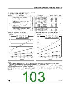
14.4.3 HALT Mode
1)
Symbol
Parameter
Conditions
-40°C≤T ≤+85°C
Typ
Max
10
Unit
A
V
V
=5.5V
=3.6V
DD
-40°C≤T ≤+125°C
150
6
A
2)
I
Supply current in HALT mode
0
µA
DD
-40°C≤T ≤+85°C
A
DD
-40°C≤T ≤+125°C
100
A
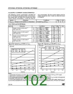
14.4.4 Supply and Clock Managers
The previous current consumption specified for
the ST7 functional operating modes over tempera-
ture range does not take into account the clock
source current consumption. To get the total de-
vice consumption, the two current values must be
added (except for HALT mode).
1)
3)
Symbol
Parameter
Conditions
Typ
Max
Unit
Supply current of internal RC oscillator
Supply current of external RC oscillator
500
525
750
750
4)
200
300
450
700
400
550
750
LP: Low power oscillator
I
DD(CK)
MP: Medium power oscillator
MS: Medium speed oscillator
HS: High speed oscillator
4) & 5)
Supply current of resonator oscillator
µA
1000
Clock security system supply current
LVD supply current
150
100
350
150
I
HALT mode
DD(LVD)
14.4.5 On-Chip Peripherals
Symbol
Parameter
Conditions
Typ
50
Unit
V
V
V
V
V
V
V
V
=3.4V
=5.0V
=3.4V
=5.0V
=3.4V
=5.0V
=3.4V
=5.0V
DD
DD
DD
DD
DD
DD
DD
DD
6)
I
16-bit Timer supply current
f
f
f
f
=8MHz
=8MHz
=8MHz
=4MHz
DD(TIM)
CPU
CPU
CPU
ADC
150
250
350
250
350
800
1100
7)
I
SPI supply current
DD(SPI)
µA
2
8)
I
I C supply current
DD(I2C)
9)
I
ADC supply current when converting
DD(ADC)
Notes:
1. Typical data are based on T =25°C.
A
2. All I/O pins in input mode with a static value at V or V (no load), CSS and LVD disabled. Data based on charac-
DD
SS
CPU
terization results, tested in production at V max. and f
max.
DD
3. Data based on characterization results, not tested in production.
4. Data based on characterization results done with the external components specified in Section 14.5.3 and Section
14.5.4, not tested in production.
5. As the oscillator is based on a current source, the consumption does not depend on the voltage.
6. Data based on a differential I measurement between reset configuration (timer counter running at f
/4) and timer
DD
CPU
counter stopped (selecting external clock capability). Data valid for one timer.
7. Data based on a differential I measurement between reset configuration and a permanent SPI master communica-
DD
tion (data sent equal to 55h).
8. Data based on a differential I measurement between reset configuration and I2C peripheral enabled (PE bit set).
DD
9. Data based on a differential I measurement between reset configuration and continuous A/D conversions.
DD
104/140

 ETC [ ETC ]