ST6200C/ST6201C/ST6203C
3 MEMORY MAPS, PROGRAMMING MODES AND OPTION BYTES
3.1 MEMORY AND REGISTER MAPS
3.1.1 Introduction
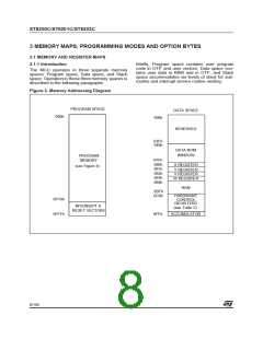
Briefly, Program space contains user program
code in OTP and user vectors; Data space con-
tains user data in RAM and in OTP, and Stack
space accommodates six levels of stack for sub-
routine and interrupt service routine nesting.
The MCU operates in three separate memory
spaces: Program space, Data space, and Stack
space. Operation in these three memory spaces is
described in the following paragraphs.
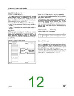
Figure 3. Memory Addressing Diagram
PROGRAM SPACE
000h
DATA SPACE
000h
RESERVED
03Fh
040h
DATA ROM
WINDOW
PROGRAM
MEMORY
07Fh
080h
081h
082h
083h
084h
X REGISTER
Y REGISTER
V REGISTER
W REGISTER
(see Figure 4)
RAM
0BFh
0C0h
HARDWARE
CONTROL
REGISTERS
0FF0h
INTERRUPT &
(see Table 2)
RESET VECTORS
0FFFh
ACCUMULATOR
0FFh
8/104
1

 ETC [ ETC ]