ST6200C/ST6201C/ST6203C
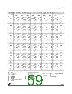
10 INSTRUCTION SET
10.1 ST6 ARCHITECTURE
The ST6 architecture has been designed for max-
imum efficiency while keeping byte usage to a
minimum; in short, to provide byte-efficient pro-
gramming. The ST6 core has the ability to set or
clear any register or RAM location bit in Data
space using a single instruction. Furthermore, pro-
grams can branch to a selected address depend-
ing on the status of any bit in Data space.
tended addressing mode are able to branch to any
address in the 4 Kbyte Program space.
Extended addressing mode instructions are two
bytes long.
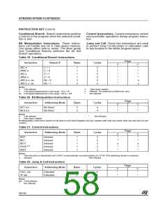
Program Counter Relative. Relative addressing
mode is only used in conditional branch instruc-
tions. The instruction is used to perform a test and,
if the condition is true, a branch with a span of -15
to +16 locations next to the address of the relative
instruction. If the condition is not true, the instruc-
tion which follows the relative instruction is execut-
ed. Relative addressing mode instructions are one
byte long. The opcode is obtained by adding the
three most significant bits which characterize the
test condition, one bit which determines whether it
is a forward branch (when it is 0) or backward
branch (when it is 1) and the four least significant
bits which give the span of the branch (0h to Fh)
which must be added or subtracted from the ad-
dress of the relative instruction to obtain the
branch destination address.
10.2 ADDRESSING MODES
The ST6 has nine addressing modes, which are
described in the following paragraphs. Three dif-
ferent address spaces are available: Program
space, Data space, and Stack space. Program
space contains the instructions which are to be ex-
ecuted, plus the data for immediate mode instruc-
tions. Data space contains the Accumulator, the X,
Y, V and W registers, peripheral and Input/Output
registers, the RAM locations and Data ROM loca-
tions (for storage of tables and constants). Stack
space contains six 12-bit RAM cells used to stack
the return addresses for subroutines and inter-
rupts.
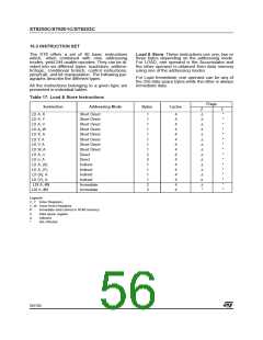
Bit Direct. In bit direct addressing mode, the bit to
be set or cleared is part of the opcode, and the
byte following the opcode points to the address of
the byte in which the specified bit must be set or
cleared. Thus, any bit in the 256 locations of Data
space memory can be set or cleared.
Immediate. In immediate addressing mode, the
operand of the instruction follows the opcode loca-
tion. As the operand is a ROM byte, the immediate
addressing mode is used to access constants
which do not change during program execution
(e.g., a constant used to initialize a loop counter).
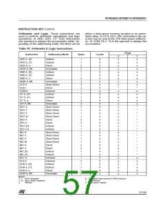
Bit Test & Branch. Bit test and branch addressing
mode is a combination of direct addressing and
relative addressing. Bit test and branch instruc-
tions are three bytes long. The bit identification
and the test condition are included in the opcode
byte. The address of the byte to be tested is given
in the next byte. The third byte is the jump dis-
placement, which is in the range of -127 to +128.
This displacement can be determined using a la-
bel, which is converted by the assembler.
Direct. In direct addressing mode, the address of
the byte which is processed by the instruction is
stored in the location which follows the opcode. Di-
rect addressing allows the user to directly address
the 256 bytes in Data Space memory with a single
two-byte instruction.
Short Direct. The core can address the four RAM
registers X, Y, V, W (locations 80h, 81h, 82h, 83h)
in short-direct addressing mode. In this case, the
instruction is only one byte and the selection of the
location to be processed is contained in the op-
code. Short direct addressing is a subset of direct
addressing mode. (Note that 80h and 81h are also
indirect registers).
Indirect. In indirect addressing mode, the byte
processed by the register-indirect instruction is at
the address pointed to by the content of one of the
indirect registers, X or Y (80h, 81h). The indirect
register is selected by bit 4 of the opcode. Register
indirect instructions are one byte long.
Extended. In extended addressing mode, the 12-
bit address needed to define the instruction is ob-
tained by concatenating the four least significant
bits of the opcode with the byte following the op-
code. The instructions (JP, CALL) which use ex-
Inherent. In inherent addressing mode, all the in-
formation necessary for executing the instruction
is contained in the opcode. These instructions are
one byte long.
55/104
1

 ETC [ ETC ]