IP1001 LF
Data Sheet
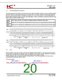
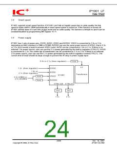
3.3
Serial Management Interface
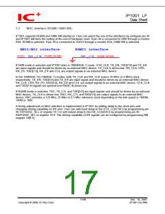
The serial management interface consisting of two pins, MDC and MDIO, provides access to the MII registers
of IP1001. MDC is a clock input and runs at a maximum rate of 12.5 MHz. MDIO is a bi-directional data pin
that runs synchronously to MDC. The MDIO pin requires a 5.1-kΩ pull up resistor. To access MII register in
IP1001, MDC should be at least one more cycle than MDIO. That is, a complete command consists of 32 bits
MDIO data and at least 33 MDC clocks.
Frame
format
<Idle><start><op code><PHY address><Registers address><turnaround><data><idle>
Read
Operation
<Idle><01><10><A4A3A2A1A0><R4R3R2R1R0><Z0><b15 b14 b13 b12 b11 b10 b9 b8 b7 b6 b5 b4 b3 b2 b1b0><Idle>
<Idle><01><01><A4A3A2A1A0><R4R3R2R1R0><10><b15 b14 b13 b12 b11 b10 b9 b8 b7 b6 b5 b4 b3 b2 b1b0><Idle>
Write
Operation
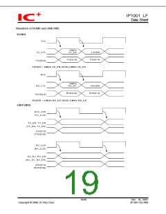
MDC
z
z
MDIO
1..1
1..1
0 0 0 0
0 0
0
0
0
0 0 1
0
0 1 1 0 0
0 1
1
0
0 1 0 0 0
0
0 1 1 0
op
code
A A A A A R R R R R
4 3 2 1 0 4 3 2 1 0
b b b b b b b b b b b b b b b b
1 1 1 1 1 1 9 8 7 6 5 4 3 2 1 0
idle
idle
start
TA
write
PHY address =
01h
Reg address =
00h
5 4 3 2 1 0
Register data
MDC
z
z
z
MDIO
1..1
1..1
0 0 0 0
0 0
1
0
0
0 0 Z
0
0 0 1 0 0
0 1
0
0
0 1 0 0 0
0
0 1 1 0
op
code
A A A A A R R R R R
4 3 2 1 0 4 3 2 1 0
b b b b b b b b b b b b b b b b
1 1 1 1 1 1 9 8 7 6 5 4 3 2 1 0
idle
idle
start
TA
read
PHY address =
01h
Reg address =
00h
5 4 3 2 1 0
Register data
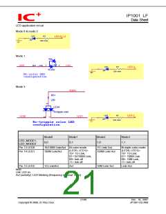
3.4
LED
IP1001 provides 3 LED pins, LED0~2, and four LED display modes, mode0~3. User can select one of four
LED modes by configuring LED_MODE1 and LED_MODE0. LED_MODE1 and LED_MODE0 are defined in
register 16[15:14]. Pin 55 LED_MODE0 defines the default value of register 16[14].
The functionality of the LED pins is shown in the table below. The driving capability of LED pins can be
programmed by writing MII register 16[13].
LED mode setting
LED mode 1
LED mode 0
VDDO
R24 5.1K TX_CLK/LED_MODE0
R44 5.1K TX_CLK/LED_MODE0
20/48
Dec. 18, 2007
IP1001-DS-R06
Copyright © 2006, IC Plus Corp.

 ETC [ ETC ]