HT1621
enter the power down mode, similar to the case
in the external 256kHz clock source operation.
At the initial system power on, the HT1621 is at
the SYS DIS state.
where the value of n ranges from 0 to 7 by com-
mand options. The 32kHz in the above equation
indicates that the source of the system fre-
quency is derived from a crystal oscillator of
32.768kHz, an on-chip oscillator (256kHz), or
an external frequency of 256kHz.
Time base and Watchdog Timer (WDT)
The time base generator is comprised by an
8-stage count-up ripple counter and is designed
to generate an accurate time base. The watch
dog timer (WDT), on the other hand, is com-
posed of an 8-stage time base generator along
with a 2-stage count-up counter, and is de-
signed to break the host controller or other sub-
systems from abnormal states such as
unknown or unwanted jump, execution errors,
etc. The WDT time-out will result in the setting
of an internal WDT time-out flag. The outputs
of the time base generator and of the WDT
time-out flag can be connected to the IRQ out-
put by a command option. There are totally
eight frequency sources available for the time
base generator and the WDT clock. The fre-
quency is calculated by the following equation.
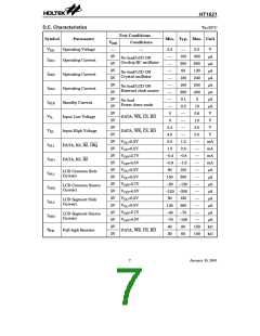
If an on-chip oscillator (256kHz) or an external
256kHz frequency is chosen as the source of the
system frequency, the frequency source is by de-
fault prescaled to 32kHz by a 3-stage prescaler.
Employing both the time base generator and
the WDT related commands, one should be
careful since the time base generator and WDT
share the same 8-stage counter. For example,
invoking the WDT DIS command disables the
time base generator whereas executing the
WDT EN command not only enables the time
base generator but activates the WDT time-out
flag output (connect the WDT time-out flag to
the IRQ pin). After the TIMER EN command is
transferred, the WDT is disconnected from the
IRQ pin, and the output of the time base generator
is connected to the IRQ pin. The WDT can be
cleared by executing the CLR WDT command,
and the contents of the time base generator is
cleared by executing the CLR WDT or the CLR
32kHz
2n
fWDT
=
C
r
y
s
t
a
l
O
s
c
i
l
l
a
t
o
r
O
S
C
I
3
2
7
6
8
H
z
O
S
C
O
E
x
t
e
r
n
a
l
C
l
o
c
k
S
o
u
r
c
e
S
C
y
s
t
c
e
m
2
5
6
k
H
z
l
o
k
1
/
8
O
n
-
c
h
i
p
R
C
O
s
c
i
l
l
a
t
o
r
2
5
6
k
H
z
System oscillator configuration
T
i
m
e
r
/
W
D
T
T
I
M
E
R
E
N
/
D
I
S
C
l
o
c
k
S
o
u
r
c
e
s
S
f
y
s
t
e
m
C
l
o
c
k
n
/
2
5
6
I
R
Q
/
2
W
D
D
T
E
N
/
D
I
S
=
3
2
k
H
z
n
=
0
~
7
V
D
Q
D
W
D
T
I
R
Q
E
N
/
D
I
S
C
K
/
4
R
C
L
R
W
D
T
Timer and WDT configurations
10
January 10, 2001

 ETC [ ETC ]