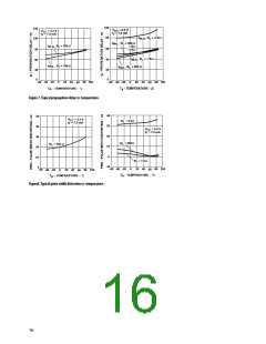
V
Likewise for common-mode transients which occur
when the LED is off (i.e. CMR , since the output is“high”),
CC
H
HCPL-260L
if an imbalance between I and I results in a transient
LP
LN
1
2
420 Ω
I equal to or greater than the switching threshold of the
(MAX)
F
optocoupler, the transient“signal”may cause the output
2N3906
(ANY PNP)
to spike below 2 V (which constitutes a CMR failure).
H
74L504
(ANY
LED
TTL/CMOS
GATE)
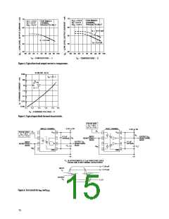
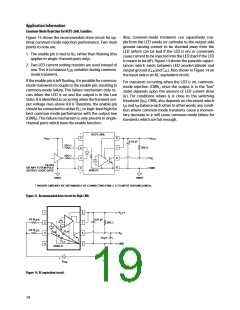
By using the recommended circuit in Figure 13, good
3
4
CMR can be achieved. The balanced I -setting resistors
LED
help equalize I and I to reduce the amount by which
LP
LN
I
is modulated from transient coupling through C
LED
LA
and C .
LC
CMR with Other Drive Circuits
CMR performance with drive circuits other than that
shown in Figure 13 may be enhanced by following these
guidelines:
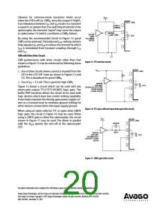
Figure 15. TTL interface circuit.
V
CC
HCPL-260L
1. Use of drive circuits where current is shunted from the
LED in the LED “off” state (as shown in Figures 15 and
1
2
R
16). This is beneficial for good CMR .
H
2. Use of I > 3.5 mA. This is good for high CMR .
FH
L
74HC00
(OR ANY
LED
Figure 15 shows a circuit which can be used with any
totem-pole-output TTL/LSTTL/HCMOS logic gate. The
buffer PNP transistor allows the circuit to be used with
logic devices which have low current-sinking capability.
It also helps maintain the driving-gate power-supply cur-
rent at a constant level to minimize ground shifting for
other devices connected to the input-supply ground.
OPEN-COLLECTOR/
OPEN-DRAIN
3
4
LOGIC GATE)
Figure 16. TTL open-collector/open drain gate drive circuit.
When using an open-collector TTL or open-drain CMOS
logic gate, the circuit in Figure 16 may be used. When
using a CMOS gate to drive the optocoupler, the circuit
shown in Figure 17 may be used. The diode in parallel
V
CC
HCPL-260L
1N4148
1
2
with the R
LED.
speeds the turn-off of the optocoupler
LED
220 Ω
74HC04
(OR ANY
LED
TOTEM-POLE
OUTPUT LOGIC
GATE)
3
4
Figure 17. CMOS gate drive circuit.
For product information and a complete list of distributors, please go to our website: www.avagotech.com
Avago, Avago Technologies, and the A logo are trademarks of Avago Technologies Limited in the United States and other countries.
Data subject to change. Copyright © 2007 Avago Technologies Limited. All rights reserved. Obsoletes AV01-0581EN
AV02-0616EN - December 19, 2007

 ETC [ ETC ]