PRELIMINARY PRODUCT SPECIFICATION
nRF24L01 Single Chip 2.4 GHz Radio Transceiver
2. After 130µs nRF24L01 is monitoring the air for incoming communication.
3. When a valid packet has been received (matching address and correct CRC), the
payload is stored in the RX-FIFO, and the RX_DR bit in status register is set high.
The IRQ pin will be active when RX_DR is high. RX_P_NO in status register will
indicate what data pipe the payload has been received in.
4. If auto acknowledgement is enabled, an acknowledgement is sent back.
5. MCU sets the CE pin low to enter Standby-I mode (low current mode).
6. MCU can clock out the payload data at a suitable rate via the SPI interface.
7. The device is now ready for entering TX or RX mode or power down mode.
Auto Acknowledgement (RX)
The auto acknowledgement function reduces the load of the external microcontroller,
and may remove the need for dedicated SPI hardware in a mouse/keyboard or
comparable systems, and hence reduce cost and average current consumption. Auto
acknowledgement can be configured individually for each data pipe via the SPI
interface.
If auto acknowledgement is enabled and a valid packet (correct data pipe address and
CRC) is received, the device will enter TX mode and send an acknowledgement
packet. After the device has sent the acknowledgement packet, normal operation
resumes, and the mode is determined by the PRIM_RX register and CE pin.
Auto Re-Transmission (ART) (TX)
An auto retransmission function is available. It will be used at the TX side in an auto
acknowledgement system. In the SETUP_RETR register it will be possible to state
how many times the data in the data register will be resent if data is not
acknowledged. After each sending, the device will enter RX mode and wait a
specified time period for acknowledgement. When the acknowledgement packet is
received, the device will return to normal transmit function. If there is no more unsent
data in the TX FIFO and the CE pin is low, the device will go into Standby-I mode. If
the acknowledgement is not received, the device will go back to TX mode and resend
the data. This will continue until acknowledgment is received, or a time out occurs
(i.e. the maximum number of sending is reached). The only way to reset this is to set
the PWR_UP bit low or let the auto retransmission finish. A packet loss counter will
be incremented each time a packet does not succeed to reach the destination before
time out. (Time out is indicated by the MAX_RT interrupt.) The packet loss counter is
reset when writing to the RF channel register.
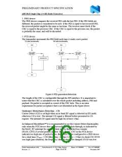
Packet Identity (PID) and CRC used by Enhanced ShockBurstTM
Each packet contains a two bit wide PID field to detect if the received packet is new
or resent. The PID will prevent that the PRX device presents the same payload more
than once to the microcontroller. This PID field is incremented at the TX side for each
new packet received via the SPI interface. The PID and CRC field is used by the PRX
device to determine whether a packet is resent or new. When several data is lost on
the link, the PID fields may in some cases become equal to last received PID. If a
packet has the same PID as the previous packet, nRF24L01 will compare the CRC
sums from both packets. If they also are equal, the last received packet is considered
as a copy of the previous and is discarded.
Nordic Semiconductor ASA - Vestre Rosten 81, N-7075 Tiller, Norway
Revision: 1.1
-
Phone +4772898900
-
Fax +4772898989
November 2005
Page 15 of 38

 ETC [ ETC ]