PRELIMINARY PRODUCT SPECIFICATION
nRF24L01 Single Chip 2.4 GHz Radio Transceiver
Enhanced ShockBurst™ Transmitting Payload:
1. The configuration bit PRIM_RX has to be low.
2. When the application MCU has data to send, the address for receiving node
(TX_ADDR) and payload data (TX_PLD) has to be clocked into nRF24L01 via
the SPI interface. The width of TX-payload is counted from number of bytes
written into the TX FIFO from the MCU. TX_PLD must be written continuously
while holding CSN low. TX_ADDR does not have to be rewritten if it is
unchanged from last transmit. If the PTX device shall receive acknowledge, data
pipe 0 has to be configured to receive the acknowledge. The receive address for
data pipe 0 (RX_ADDR_P0) has to be equal to the transmit address (TX_ADDR)
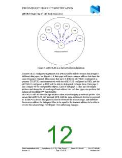
in the PTX device. For the example in Figure 5 the following address settings
have to be performed for the TX5 device and the RX device:
TX5 device: TX_ADDR = 0xB3B4B5B605
TX5 device: RX_ADDR_P0 = 0xB3B4B5B605
RX device: RX_ADDR_P5 = 0xB3B4B5B605
3. A high pulse on CE starts the transmission. The minimum pulse width on CE is 10 µs.
4. nRF24L01 ShockBurst™:
•
•
•
•
Radio is powered up
16 MHz internal clock is started.
RF packet is completed (see the packet description)
Data is transmitted at high speed (1 Mbps or 2 Mbps configured by MCU).
5. If auto acknowledgement is activated (Auto retransmit counter not equal zero,
ENAA_P0=1) the radio goes into RX mode immediately. If a valid packet has
been received in the valid acknowledgement time window, the transmission is
considered a success. The TX_DS bit in the status register is set high and the
payload is removed from TX FIFO. If a valid acknowledgement is not received in
the specified time window, the payload is resent (if auto retransmit is enabled). If
the auto retransmit counter (ARC_CNT) exceeds the programmed maximum limit
(ARC), the MAX_RT bit in the status register is set high. The payload in TX
FIFO is NOT removed. The IRQ pin will be active when MAX_RT or TX_DS is
high. To turn off the IRQ pin, the interrupt source must be reset by writing to the
status register (see Interrupt chapter). If no acknowledgement is received for a
packet after the maximum number of retries, no further packets can be sent before
the MAX_RX interrupt is cleared. The packet loss counter (PLOS_CNT) is
incremented at each MAX_RT interrupt. I.e. ARC_CNT counts the number of
retries that was required to get a single packet through. PLOS_CNT counts the
number of packets that did not get through even after maximum number of retries.
6. The device goes into Standby-I mode if CE is low. Otherwise next payload in TX
FIFO will be sent. If TX FIFO is empty and CE is still high, the device will enter
Standby-II mode.
7. If the device is in Standby-II mode, it will go to Standby-I mode immediately if
CE is set low.
Enhanced ShockBurstTM Receive Payload:
1. RX is selected by setting the PRIM_RX bit in the configuration register to high,
and then setting CE high.
Nordic Semiconductor ASA - Vestre Rosten 81, N-7075 Tiller, Norway
Revision: 1.1
-
Phone +4772898900
-
Fax +4772898989
November 2005
Page 14 of 38

 ETC [ ETC ]