a-Si TFT LCD Single Chip Driver
240RGBx320 Resolution and 262K color
ILI9325
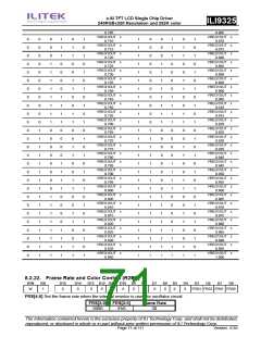
NL[5:0]
LCD Drive Line
240 lines
6’h1D
6’h1E
6’h1F
6’h20
6’h21
6’h22
6’h23
6’h24
6’h25
6’h26
6’h27
Others
248 lines
256 lines
264 lines
272 lines
280 lines
288 lines
296 lines
304 lines
312 line
320 line
Setting inhibited
NDL: Sets the source driver output level in the non-display area.
Non-Display Area
NDL
Positive Polarity
Negative Polarity
0
1
V63
V0
V0
V63
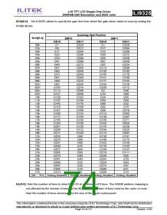
GS: Sets the direction of scan by the gate driver in the range determined by SCN[4:0] and NL[4:0]. The scan
direction determined by GS = 0 can be reversed by setting GS = 1.
When GS = 0, the scan direction is from G1 to G320.
When GS = 1, the scan direction is from G320 to G1
REV: Enables the grayscale inversion of the image by setting REV=1.
Source Output in Display Area
REV GRAM Data
Positive polarity negative polarity
18’h00000
V63
V0
.
.
.
0
1
.
.
.
.
.
.
V0
V0
.
18’h3FFFF
18’h00000
V63
V63
.
.
.
.
.
.
.
.
18’h3FFFF
V63
V0
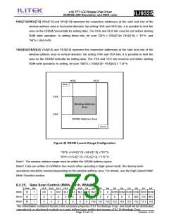
VLE: Vertical scroll display enable bit. When VLE = 1, the ILI9325 starts displaying the base image from the
line (of the physical display) determined by VL[8:0] bits. VL[8:0] sets the amount of scrolling, which is the
number of lines to shift the start line of the display from the first line of the physical display. Note that the
partial image display position is not affected by the base image scrolling.
The vertical scrolling is not available in external display interface operation. In this case, make sure to
set VLE = “0”.
VLE
Base Image Display
The information contained herein is the exclusive property of ILI Technology Corp. and shall not be distributed,
reproduced, or disclosed in whole or in part without prior written permission of ILI Technology Corp.
Page 75 of 111
Version: 0.35

 ETC [ ETC ]