a-Si TFT LCD Single Chip Driver
240RGBx320 Resolution and 262K color
ILI9325
0
1
Fixed
Enable Scrolling
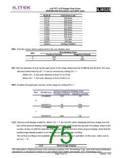
VL[8:0]: Sets the scrolling amount of base image. The base image is scrolled in vertical direction and
displayed from the line determined by VL[8:0]. Make sure that VL[8:0] ≦320.
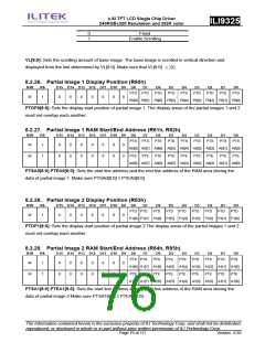
8.2.26. Partial Image 1 Display Position (R80h)
R/W
RS
D15 D14 D13 D12 D11 D10 D9 D8
D7
D6
D5
D4
D3
D2
D1
D0
PTD PTD
PTD
PTD
PTD
PTD
PTD
PTD
PTD
W
1
0
0
0
0
0
0
0
P0[8] P0[7] P0[6] P0[5] P0[4] P0[3] P0[2] P0[1] P0[0]
PTDP0[8:0]: Sets the display start position of partial image 1. The display areas of the partial images 1 and 2
must not overlap each another.
8.2.27. Partial Image 1 RAM Start/End Address (R81h, R82h)
R/W
RS
D15 D14 D13 D12 D11 D10 D9 D8
D7
D6
D5
D4
D3
D2
D1
D0
PTS PTS
PTS
PTS
PTS
PTS
PTS
PTS
PTS
W
1
0
0
0
0
0
0
0
0
0
0
0
0
0
0
A0[8] A0[7] A0[6] A0[5] A0[4] A0[3] A0[2] A0[1] A0[0]
PTE PTE PTE PTE PTE PTE PTE PTE PTE
A0[8] A0[7] A0[6] A0[5] A0[4] A0[3] A0[2] A0[1] A0[0]
W
1
PTSA0[8:0] PTEA0[8:0]: Sets the start line address and the end line address of the RAM area storing the
data of partial image 1. Make sure PTSA0[8:0] ≤ PTEA0[8:0].
8.2.28. Partial Image 2 Display Position (R83h)
R/W
RS
D15 D14 D13 D12 D11 D10 D9 D8
D7
D6
D5
D4
D3
D2
D1
D0
PTD PTD
PTD
PTD
PTD
PTD
PTD
PTD
PTD
W
1
0
0
0
0
0
0
0
P1[8] P1[7] P1[6] P1[5] P1[4] P1[3] P1[2] P1[1] P1[0]
PTDP1[8:0]: Sets the display start position of partial image 2 The display areas of the partial images 1 and 2
must not overlap each another.
8.2.29. Partial Image 2 RAM Start/End Address (R84h, R85h)
R/W
RS
D15 D14 D13 D12 D11 D10 D9 D8
D7
D6
D5
D4
D3
D2
D1
D0
PTS PTS
PTS
PTS
PTS
PTS
PTS
PTS
PTS
W
1
0
0
0
0
0
0
0
0
0
0
0
0
0
0
A1[8] A1[7] A1[6] A1[5] A1[4] A1[3] A1[2] A1[1] A1[0]
PTE PTE PTE PTE PTE PTE PTE PTE PTE
A1[8] A1[7] A1[6] A1[5] A1[4] A1[3] A1[2] A1[1] A1[0]
W
1
PTSA1[8:0] PTEA1[8:0]: Sets the start line address and the end line address of the RAM area storing the
data of partial image 2 Make sure PTSA1[8:0] ≤ PTEA1[8:0].
The information contained herein is the exclusive property of ILI Technology Corp. and shall not be distributed,
reproduced, or disclosed in whole or in part without prior written permission of ILI Technology Corp.
Page 76 of 111
Version: 0.35

 ETC [ ETC ]