CY545 Stepper System Controller
www.ControlChips.com
Notice that every character of a command takes one memory location, and all characters must
be counted to compute the target address for the Loop command.
The program then punches a hole at the last position, moves an additional 200 steps, and
activates the User Bit 2 signal to cut the strip.
Now the CY545 returns the motor to the starting position. It then tests User Bit 4, and if the
signal is low, the program repeats from the Wait instruction. If the signal is high, the program
stops with the Zero command, and the CY545 returns to the command mode.
Driver Circuit Considerations
The CY545 provides the timing and logical signals necessary to control a stepper motor.
However, to make a complete system, a driver circuit must be added to the CY545. This circuit
will take the logical signals generated by the CY545 and translate them into the high-power
signals needed to run the motor.
The user has two choices in the selection of driver circuits. Existing designs, usually in the form
of pulse-to-step translators, may be used, or special designs may be created. Translators
usually require a pulse and direction input, or two pulse streams, one for CW stepping and one
for CCW stepping. The translator takes the pulse inputs and generates the proper four-phase
outputs for the motor. Note that it is also possible to drive motors with this scheme which are not
four-phase designs. Since the translator generates the actual motor driver signals, it only
requires the pulse timing and direction information generated by the CY545 PULSE and CCW
signals. This allows the CY545 to control three and five-phase motors as well as the standard
four-phase designs.
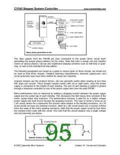
If the user opts for his own driver design, the PULSE and CCW lines may be used to drive a
counter circuit, which counts up or down once for each pulse, based on the level of the CCW
signal. The counter output then drives the address lines of a memory device, such as a PROM,
EPROM, or EEPROM, with data outputs that generate the desired motor phase patterns as the
counter address steps through the PROM locations. This design is shown here.
© 2002 Cybernetic Micro Systems
89
Chapter 19 - Circuits and Examples

 ETC [ ETC ]