CY545 Stepper System Controller
www.ControlChips.com
The second basic type of driver circuit is the bipolar design. In this case, the motor is driven only
from the ends of each winding, with switching logic used to control the direction of current
through the winding. These circuits may be implemented with a four lead motor, since only the
ends of each winding are needed.
Bipolar designs are more efficient in driving the motor, and result in higher performance than the
unipolar designs. There is also some gain in torque, since the entire winding is always driven,
unlike the unipolar design, in which only half of a winding is used at a time.
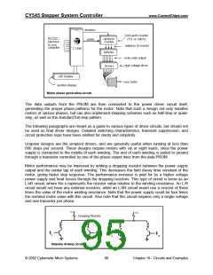
Two methods of switching the direction of current may be used. With a single voltage power
supply, eight transistors are used, two per phase. Transistors are turned on in alternate pairs
across each winding to control the current. The second alternative uses only four transistors, but
requires a dual voltage power supply. In this case, one side of each winding is connected to
ground, and the other side is switched between the positive and negative power supplies. In
both designs it is very important to insure that both transistors on one side of the winding are not
on at the same time, as this would short the power supply through the transistors, generally
destroying the transistors in the process. Protection logic is usually included to insure that one
transistor is off before the other is allowed to turn on.
The most advanced driver designs are variations on the unipolar or bipolar types, although they
are generally implemented using the bipolar approach. These drivers are capable of the highest
step rates attainable. They work by switching current or voltage through the motor at much
higher than the rated value. This is done for only a short period of time, causing the magnetic
field in the motor to change very quickly, without exceeding the maximum power dissipation of
the motor. As long as the average dissipation does not exceed the motor rating, the motor will
perform without problems. Once the maximum limit is reached, the motor may overheat and self
destruct.
One technique for increasing motor performance would simply apply a high voltage to the motor
at the beginning of each step. This makes the motor react very quickly to the change in phase
signals. After a short period of time, the voltage is switched to a lower value, allowing the motor
to continue it’s step without overheating.
A second approach, known as a constant current design, senses the amount of current flowing
through the winding, and adjusts the voltage applied to the motor to maintain the current at its
maximum rated value. At the beginning of a motion, the voltage would be low, with a constant
adjustment to a higher value as the motor speed increases, and back EMF decreases the
current draw for a fixed voltage level.
© 2002 Cybernetic Micro Systems
91
Chapter 19 - Circuits and Examples

 ETC [ ETC ]