CY545 Stepper System Controller
www.ControlChips.com
CHAPTER 18 - ELECTRICAL SPECIFICATIONS
CY545B Electrical Specifications
Absolute Maximum Ratings
Ambient Temperature under bias ................. 0C to +70C
Storage Temperature ................................... -65C to +150C
Voltage on any pin with respect to ground ... -0.5V to Vcc+0.5V
Power dissipation ......................................... 1.0 Watts
DC & Operating Characteristics
(TA = 0C to +70C, Vcc = +5V +/-10%)
Electrical Conventions
All CY545 signals are based on a positive logic convention, with a high voltage representing a
"1" and a low voltage representing a "0". Signals that are active low are indicated by a bar over
or slash after the pin name, i.e., BUSY/.
All input lines except the data bus include weak pull-up resistors. If the pins are left open, the
input signals will be high. The data bus pins must have external pull-up resistors to output a high
value. Where appropriate, an input line will be considered in the floating state if the CY545 can
drive it both high and low.
The data bus is bi-directional, and is tri-state during nonactive modes. Note that data bus
signals are positive logic.
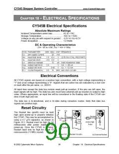
Reset Circuitry
The Restart line (pin#9) must be held
high upon power-up to properly initialize
the CY545. This may be accomplished by
using a 4.7 µFd capacitor, as shown in
Figure 18.1. Restart must be high for 10
milliseconds after power stabilizes on
power-up. Once the CY545 is running,
Restart need only be high for about 10
microseconds (11 MHz crystal).
© 2002 Cybernetic Micro Systems
85
Chapter 18 - Electrical Specifications

 ETC [ ETC ]