CY545 Stepper System Controller
www.ControlChips.com
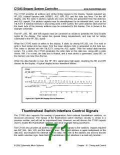
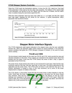
When the CY545 reads the thumbwheel switches, it drives the SW_SEL signal low. Each digit
of the parameter is then read by the two stage read operation. The address of the desired digit
is first generated, and latched by the ALE signal, then the data bus is floated, and the switch
value is enabled during the read strobe signal from RD.
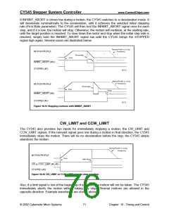
When the entire parameter value has been read, either as 3, 5, or 8 digits, the SW_SEL signal
goes high again, disabling the RD strobe for the switches. A typical thumbwheel switch
parameter read waveforms follows.
Stepper Motor Interface Signals
The CY545 implements eight signals dedicated to the stepper motor, plus the user selectable
function bits, which can generate output control signals for special hardware, or be tested for
special conditions that guide the CY545 through a program of motions, or be used for home
sensor seeking.
PULSE and CWW
The two primary control signals for the motor are PULSE and CCW, which provide the step and
direction indications to the motor. These signals are connected to the external power driver that
actually runs the motor. Every time the CY545 directs the motor to take a step, a signal is
generated on the PULSE line.
The power driver should advance the motor by one increment for each pulse. Note that the step
increment could be a full step, half step, quad step, or micro step. This will be determined by the
application and the power driver. The CY545 does not know or care what the step size is. All
position information is treated in terms of the step increment, not in terms of the linear
displacement or degrees of rotation of the motor.
The CCW signal is a level active signal that tells the power driver in which direction to step the
motor. When high, the driver should step counter clockwise, and when low, the driver should
step clockwise. Note that the physical rotation of the motor will depend on how the motor
windings are connected to the power driver, not on the level of the CCW signal. When this
signal is high, the CY545 will decrement the current position for every step taken, and when the
signal is low, it will increment the current position for every step taken.
© 2002 Cybernetic Micro Systems
67
Chapter 16 - Timing and Control

 ETC [ ETC ]