Proprietary TranSwitch Corporation Information for use Solely by its Customers
L3M
TXC-03452B
DATA SHEET
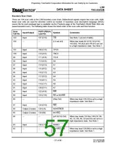
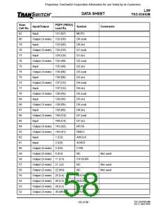
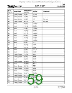
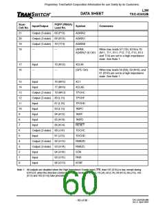
Boundary Scan Chain
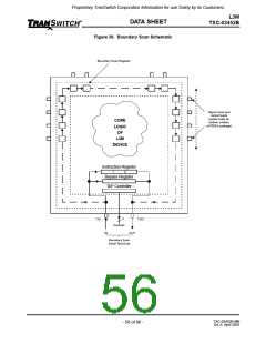
There are 104 scan cells in the L3M boundary scan chain. Bidirectional signals require two scan cells. Addi-
tional scan cells are used for direction control as needed. A boundary scan description language (BSDL)
source file for each package type is available via the Products page of the TranSwitch World Wide Web site
(www.transwitch.com). The following table shows the listed order of the scan cells and their function.
Scan
Cell No.
PQFP (PBGA)
Lead No.
Input/Output
Symbol
Comments
103
102
Input
---
107 (D16)
---
TRI
See Note 1 (at end of table).
(L3 out ctrl)
When low, leads 92 (H13), 93 (H14),
142 (B3), 143 (A2) and 144 (A1) are set
to a high impedance state. See Note 1.
101
100
99
98
97
96
95
94
93
92
91
90
89
88
Input
Input
Input
Input
Input
Input
Input
Input
Input
Input
Input
Input
Input
---
109 (C14)
110 (A15)
111 (A14)
113 (A13)
114 (D13)
115 (B12)
116 (C12)
117 (D12)
118 (B11)
119 (C11)
120 (D11)
122 (A10)
123 (C10)
---
TPOS
TNEG
TCLK
A0
A1
A2
A3
A4
A5
A6
A7
WR
RD or RD/WR
(Rdy Ctrl)
When low, lead 128 (C8) is set to a high
impedance state. See Note 1.
87
86
85
84
Input
124 (D10)
SEL
Output (3-state) 128 (C8)
Output (3-state) 129 (B8)
RDY/DTACK
INT/IRQ
---
---
(µP D(7-0) Ctrl)
When low, leads 133 thru 140 (C4, B5,
A5, C5, B6, A6, C6 and D6) are set to a
high impedance state. See Note 1.
83
82
Input
---
130 (C7)
---
RAMCI
(INT/IRQ Ctrl)
When low, lead 129 (B8) is set to a high
impedance state. See Note 1.
TXC-03452B-MB
Ed. 6, April 2001
- 57 of 96 -

 ETC [ ETC ]