3.3.3
External Interrupts
There are 13 external interrupts: IRQ4 to IRQ0 and WKP7 to WKP0.
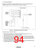
1. Interrupts WKP7 to WKP0
Interrupts WKP7 to WKP0 are requested by either rising or falling edge input to pins WKP7 to
WKP0. When these pins are designated as pins WKP7 to WKP0 in port mode register 5 and a
rising or falling edge is input, the corresponding bit in IWPR is set to 1, requesting an interrupt.
Recognition of wakeup interrupt requests can be disabled by clearing the IENWP bit to 0 in
IENR1. These interrupts can all be masked by setting the I bit to 1 in CCR.
When WKP7 to WKP0 interrupt exception handling is initiated, the I bit is set to 1 in CCR. Vector
number 9 is assigned to interrupts WKP7 to WKP0. All eight interrupt sources have the same
vector number, so the interrupt-handling routine must discriminate the interrupt source.
2. Interrupts IRQ4 to IRQ0
Interrupts IRQ4 to IRQ0 are requested by input signals to pins IRQ4 to IRQ0. These interrupts are
detected by either rising edge sensing or falling edge sensing, depending on the settings of bits
IEG4 to IEG0 in IEGR.
When these pins are designated as pins IRQ4 to IRQ0 in port mode register 3 and 1 and the
designated edge is input, the corresponding bit in IRR1 is set to 1, requesting an interrupt.
Recognition of these interrupt requests can be disabled individually by clearing bits IEN4 to IEN0
to 0 in IENR1. These interrupts can all be masked by setting the I bit to 1 in CCR.
When IRQ4 to IRQ0 interrupt exception handling is initiated, the I bit is set to 1 in CCR. Vector
numbers 8 to 4 are assigned to interrupts IRQ4 to IRQ0. The order of priority is from IRQ0 (high)
to IRQ4 (low). Table 3-2 gives details.
3.3.4
Internal Interrupts
There are 24 internal interrupts that can be requested by the on-chip peripheral modules. When a
peripheral module requests an interrupt, the corresponding bit in IRR1 or IRR2 is set to 1.
Recognition of individual interrupt requests can be disabled by clearing the corresponding bit in
IENR1 or IENR2. All these interrupts can be masked by setting the I bit to 1 in CCR. When
internal interrupt handling is initiated, the I bit is set to 1 in CCR. Vector numbers from 20 to 10
are assigned to these interrupts. Table 3-2 shows the order of priority of interrupts from on-chip
peripheral modules.
78

 ETC [ ETC ]