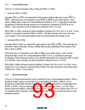
SP – 4
SP – 3
SP – 2
SP – 1
SP (R7)
SP (R7)
SP + 1
SP + 2
SP + 3
SP + 4
CCR
*
CCR
PCH
PCL
Even address
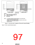
Stack area
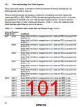
Prior to start of interrupt
exception handling
After completion of interrupt
exception handling
PC and CCR
saved to stack
Notation:
PCH: Upper 8 bits of program counter (PC)
PCL: Lower 8 bits of program counter (PC)
CCR: Condition code register
SP:
Stack pointer
1. PC shows the address of the first instruction to be executed upon
return from the interrupt handling routine.
Notes:
2. Register contents must always be saved and restored by word access,
starting from an even-numbered address.
Ignored on return.
*
Figure 3-4 Stack State after Completion of Interrupt Exception Handling
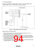
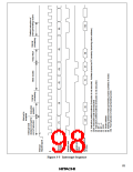
Figure 3-5 shows a typical interrupt sequence.
82

 ETC [ ETC ]