3.3.2
Interrupt Control Registers
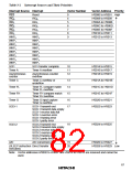
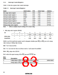
Table 3-3 lists the registers that control interrupts.
Table 3-3 Interrupt Control Registers
Name
Abbreviation
IEGR
R/W
R/W
R/W
R/W
R/W*
R/W*
R/W*
R/W
Initial Value
H'E0
Address
H'FFF2
H'FFF3
H'FFF4
H'FFF6
H'FFF7
H'FFF9
H'FF90
IRQ edge select register
Interrupt enable register 1
Interrupt enable register 2
Interrupt request register 1
Interrupt request register 2
Wakeup interrupt request register
Wakeup edge select register
IENR1
IENR2
IRR1
H'00
H'00
H'20
IRR2
H'00
IWPR
H'00
WEGR
H'00
Note:
*
Write is enabled only for writing of 0 to clear a flag.
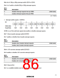
1. IRQ edge select register (IEGR)
Bit
7
—
1
6
—
1
5
—
1
4
IEG4
0
3
IEG3
0
2
1
0
IEG0
0
IEG2
0
IEG1
0
Initial value
Read/Write
—
—
—
R/W
R/W
R/W
R/W
R/W
IEGR is an 8-bit read/write register used to designate whether pins IRQ4 to IRQ0 are set to rising
edge sensing or falling edge sensing.
Bits 7 to 5: Reserved bits
Bits 7 to 5 are reserved: they are always read as 1 and cannot be modified.
Bit 4: IRQ4 edge select (IEG4)
Bit 4 selects the input sensing of the IRQ4 pin and ADTRG pin.
Bit 4
IEG4
Description
0
1
Falling edge of IRQ4 and ADTRG pin input is detected
Rising edge of IRQ4 and ADTRG pin input is detected
(initial value)
68

 ETC [ ETC ]