13.3.4
Step-Up Constant-Voltage (5 V) Power Supply
The H8/3887 Series has an on-chip step-up constant-voltage (5 V) power supply which enables a 5
V constant voltage to be obtained independently of VCC. The H8/3847 Series, however, does not
have this type of power supply.
When the SUPS bit is set to 1 in LCD control register 2 (LCR2), the step-up constant-voltage (5
V) power supply operates, and a 5 V constant voltage is output from the V0 pin. Either short the
V0 and V1 pins or connect a resistance to divide the voltage.
Note: The step-up constant-voltage (5 V) power supply must not be used for any purpose other
than the H8/3887 Series’ LCD drive power supply. In addition, when driving a large
panel, the power supply capacity may not be sufficient. In this case, use VCC as the power
supply, or use an external power supply circuit.
13.3.5
Low-Power-Consumption LCD Drive System
The use of the built-in split-resistance is normally the easiest method for implementing the LCD
power supply circuit, but since the built-in resistance is fixed, a certain direct current flows
constantly from the built-in resistance’s VCC to VSS. As this current does not depend on the current
dissipation of the LCD panel, if an LCD panel with a small current dissipation is used, a wasteful
amount of power will be consumed. The H8/3887 Series is equipped with a function to minimize
this waste of power. Use of this function makes it possible to achieve the optimum power supply
circuit for the LCD panel’s current dissipation.
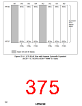
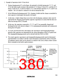
1. Principles
1. Capacitors are connected as external circuits to LCD power supply pins V1, V2, and V3, as
shown in figure 13-14.
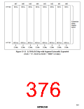
2. The capacitors connected to V1, V2, and V3 are repeatedly charged and discharged in the
cycle shown in figure 13-14, maintaining the potentials.
3. At this time, the charged potential is a potential corresponding to the V1, V2, and V3 pins,
respectively. (For example, with 1/3 bias drive, the charge for V2 is 2/3 that of V1, and that
for V3 is 1/3 that of V1.)
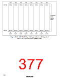
4. Power is supplied to the LCD panel by means of the charges accumulated in these
capacitors.
5. The capacitances and charging/discharging periods of these capacitors are therefore
determined by the current dissipation of the LCD panel.
6. The charging and discharging periods can be selected by software.
364

 ETC [ ETC ]