12.3.3
A/D Converter Operation Modes
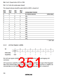
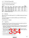
A/D converter operation modes are shown in table 12-3.
Table 12-3 A/D Converter Operation Modes
Operation
Module
Mode
Reset
Reset
Reset
Held*1
Held*1
Active
Sleep
Watch Subactive
Subsleep
Held
Standby Standby
AMR
Functions Functions Held
Functions Functions Held
Functions Functions Held
Functions Functions Held
Held
Held
Held
Held
Held
Held
Held
Held
Held
Held
Held
Held
ADSR
ADRRH
ADRRL
Held
Held
Held
Note: 1. Undefined in a power-on reset.
12.4
Interrupts
When A/D conversion ends (ADSF changes from 1 to 0), bit IRRAD in interrupt request register 2
(IRR2) is set to 1.
A/D conversion end interrupts can be enabled or disabled by means of bit IENAD in interrupt
enable register 2 (IENR2).
For further details see 3.3, Interrupts.
12.5
Typical Use
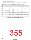
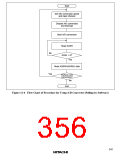
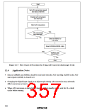
An example of how the A/D converter can be used is given below, using channel 1 (pin AN1) as
the analog input channel. Figure 12-3 shows the operation timing.
1. Bits CH3 to CH0 of the A/D mode register (AMR) are set to 0101, making pin AN1 the analog
input channel. A/D interrupts are enabled by setting bit IENAD to 1, and A/D conversion is
started by setting bit ADSF to 1.
2. When A/D conversion is complete, bit IRRAD is set to 1, and the A/D conversion result is
stored is stored in ADRRH and ADRRL. At the same time ADSF is cleared to 0, and the A/D
converter goes to the idle state.
3. Bit IENAD = 1, so an A/D conversion end interrupt is requested.
4. The A/D interrupt handling routine starts.
5. The A/D conversion result is read and processed.
339

 ETC [ ETC ]