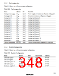
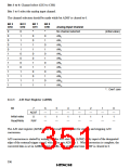
Bits 3 to 0: Channel select (CH3 to CH0)
Bits 3 to 0 select the analog input channel.
The channel selection should be made while bit ADSF is cleared to 0.
Bit 3
CH3
Bit 2
CH2
Bit 1
CH1
Bit 0
CH0
Analog Input Channel
0
0
0
0
0
1
1
1
1
1
1
1
1
0
1
1
1
1
0
0
0
0
1
1
1
1
*
*
No channel selected
(initial value)
0
0
1
1
0
0
1
1
0
0
1
1
0
1
0
1
0
1
0
1
0
1
0
1
AN0
AN1
AN2
AN3
AN4
AN5
AN6
AN7
AN8
AN9
AN10
AN11
*: Don’t care
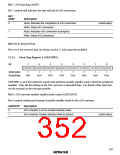
12.2.3
A/D Start Register (ADSR)
Bit
7
ADSF
0
6
—
1
5
—
1
4
—
1
3
—
1
2
—
1
1
—
1
0
—
1
Initial value
Read/Write
R/W
—
—
—
—
—
—
—
The A/D start register (ADSR) is an 8-bit read/write register for starting and stopping A/D
conversion.
A/D conversion is started by writing 1 to the A/D start flag (ADSF) or by input of the designated
edge of the external trigger signal, which also sets ADSF to 1. When conversion is complete, the
converted data is set in ADRRH and ADRRL, and at the same time ADSF is cleared to 0.
336

 ETC [ ETC ]